Week 11 - Final project
OBJECTIVES
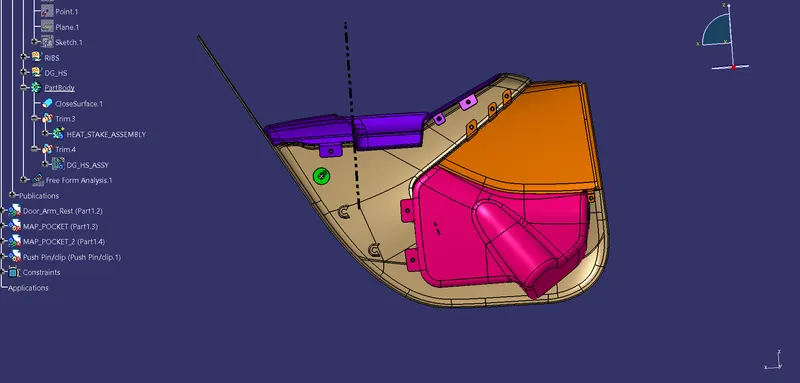
Here we have given the Class-A of all the parts that we need to work upon.The parts that we need to work upon is LOWER SUBSTRATE,DOOR ARM REST,MAP POCKET 1 ,MAP POCKET 2.We need to make the THICKENED part out of it.Then I need to create the Attachment Features on the suitable space.After all of that wed need to check the DRAFT ANALYSIS FOR THE DESIGNED PART.
PROCESS FOR DESIGNING THE COMPONENTS
LOWER SUBSTRATE
For this part before proceeding further we need to check for any irregularities in the given Class A surface such as any open boundary.merging distance between the small small patches,to do that we need to perform the Boundary operation in the Class-A surface.
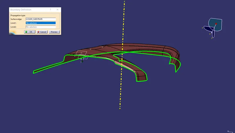
The above Fig. shows that the given class A is ready to proceed for further processes,as there are no deformities.
So now we can proceed for performing the Draft Analysis on the Class A of LOWER SUBSTRATE.
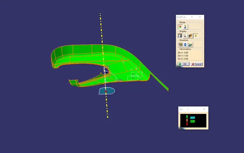
NOTE:FOR CREATION OF TOOLING AXIS I PREFER THE POINT ON THE CURVE ON THE RANDOM SURFACE AND THEN CREATE LINE BY POINT-DIRECTION METHOD.
CLASS-B
For Creation of Class-b we need to offset the Class A for 2.5mm directly and we will find our required CLASS-B.
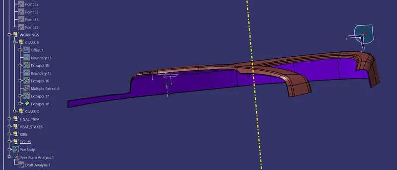
Note:The inside Violet surface is our CLASS-B.
CLASS C
Now we need to make the Class-c.Here the Class C need to be straight(90 deg from the Class-A surface).
To do that we need to perform the Sweep operation on the Class-A surface boundary.
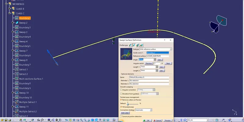
Similarly we can create for all the boundary (as the sweep can't possible as a single boundary).
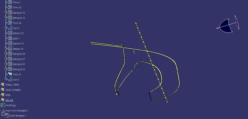
Now join the Class-A & Class-C both together to get out desired Class C.
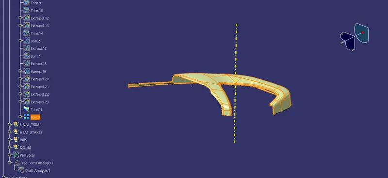
Now we have to Trim the CLASS-B to CLASS-C. to get our desired part.
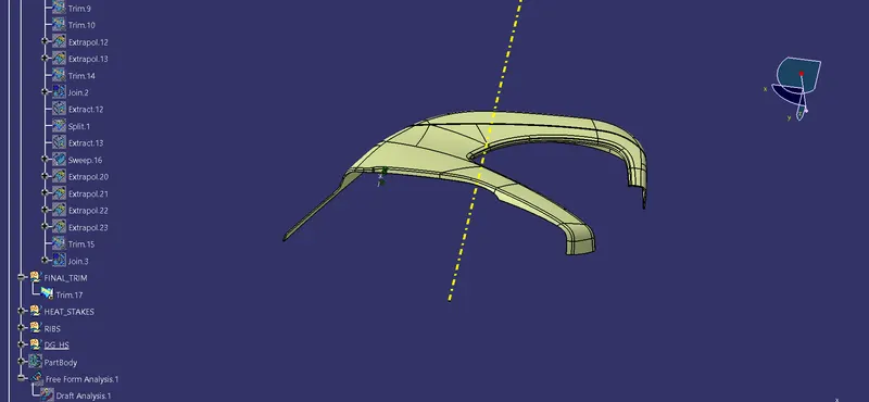
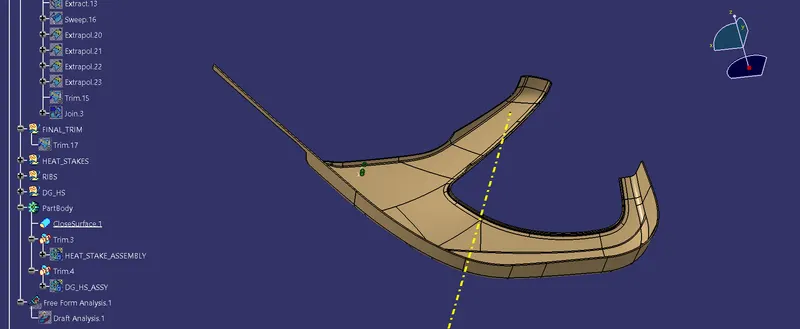
AS the top fig. shows the part is fully developed. Now convert the created surface to part body by CLOSE SURFACE BODY.
Door Arm Rest
Here also we have given the CLASS-A .to convert into part body.
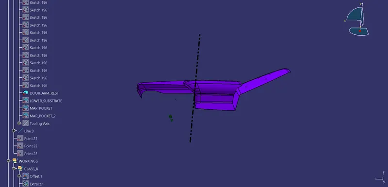
But before proceed further we need to check the Boundary for the ClassA.
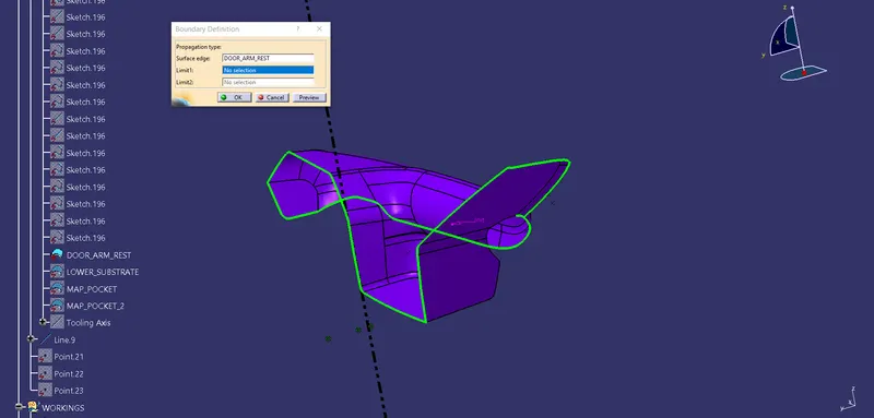
Here we can see that the side of the surface can have issue, so either we need to resolve it or we can inform to out heigher authority but here we can ignore this issue and rectify it later on.
Now we have to offset this surface to 2.5mm to get our desired CLASS B surface.
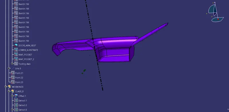
NOTE: THE BOTTOM SURFACE IS OUR CLASS B SURFACE
CLASS-C
Now we have to create the CLASS-C for this part .
To craete the Class C for the part we need to divide the boundary as small small sagments then perform the sweep operation with 90deg to get our desired Class C surfece.
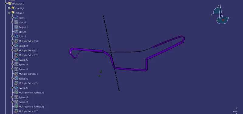
Now we have to join this above created surface to our CLASS A surface.
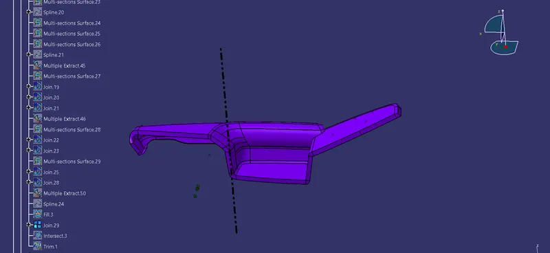
Now we have to TRIM this created part with our created CLASS B surface.
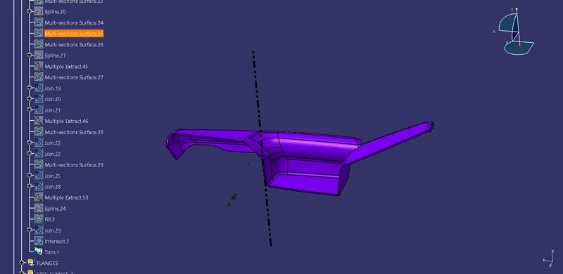
After we get or joined surface we need to make this surface into solid surface,to do that we need to perform the CLOSE SURFACE BODY operation on this part ro get our desired part.
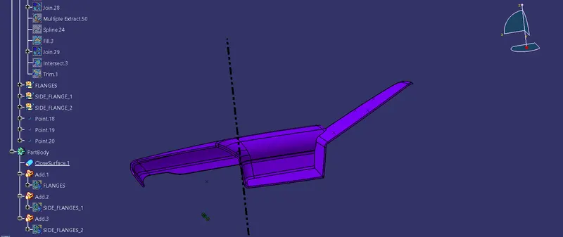
OUR DOOR ARM REST IS READY .
Now we need to assemble it to the other part so that we need to make the assembly feature(flanges).
For Flanges we need to choose the place where we need to make the flanges & with the help of that places we can assemble it perfectly.
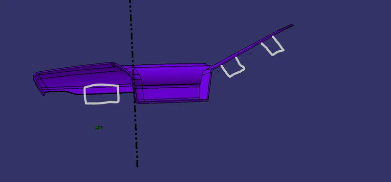
These are the places that I consider for this part to assemble it perfectly.
So to make the flanges we need to EXTRACT that area and sweep small sagements.
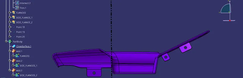
now we have to make a way for inserting the HEAT STAKES.
MAP POCKETS
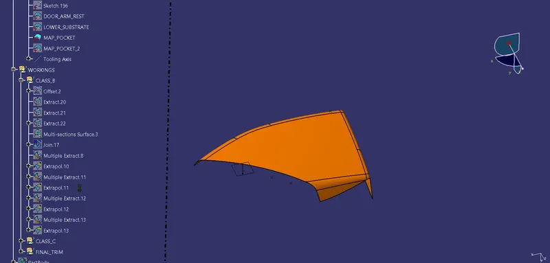
Here I have also given a Class A to work with.So we need to check the Boundary.
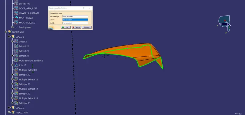
Here as the boundary is fine we can proceed for creating the CLASS B surface.
So we can create the class B by offseting the Class-A surface.
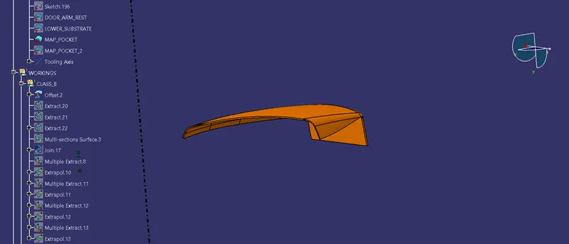
The bottom surface is our required Class-B surface.
CLASS-C
To create the class-c we need to SWEEP the bottom of the Class-a as BOUNDARY.
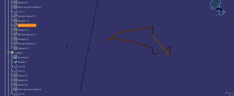
After that we have to join the Class A & Class C to get Complete Class C then Trim that Created part with Class-B.
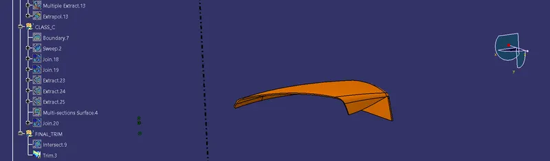
Now we have to convert this to part model by CLOSE SURFACE BODY.
This Part also need to be attached,so for that we need to make the attachment features(FLANGES).
The area that i choose for designing the Flanges are-
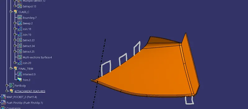
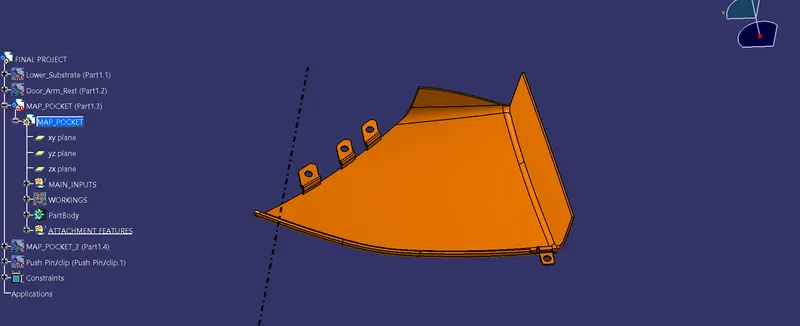
NOTE: WE CAN FOLLOW THE SAME METHODS FOR CREATING THE MAP POCKET-2 AND THE GET THE OUTPUT AS GIVEN BELOW.
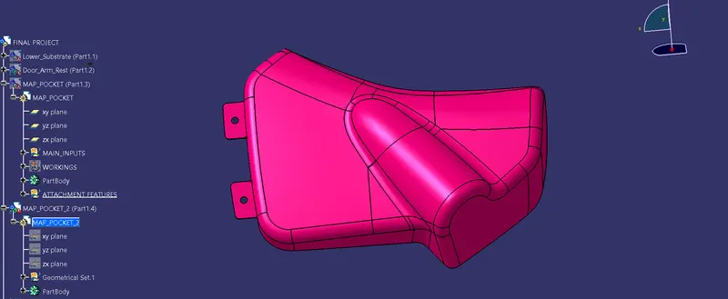
NOW ALL THE PARTS ARE READY FOR ASSEMBLE TO LOWER SUBSTRATE
NOW IN LOWER SUBSTRATE WE NEED TO MAKE HEAT STAKES FOR OTHER PARTS TO ASSEMBLE.
To do that we need to make Heat Stakes with the referenced of the Flanges hole.
Now Select the Flange POINT & create a PLANE there,
Then draw the req Sketch & pad it,then apply DRAFT on it.That padded Part can't have that much of strength so we need to add ribs to it
Then those RIBS need to be UNION TRIMMED with the HEAT STAKES.
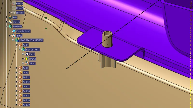
Now as this can be treated as an assembly so we can TRANSLATE this whole assembly to the every single point that we have created.
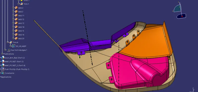
Now UNION TRIM that assembly from the Main Part so that the bottom side will not be affected.
All the parts are assembled to the Lower Substrate but What about the LOWER SUBSTRATE?
To assemble the LOWER SUBSTRATE we need to have the DOG HOUSES & PUSH PIN on top of that.
SO THE FINAL MODEL WILL LOOK LIKE ......