Week 11 - Final project
FINAL REPORT OF THE PROJECT
DEVELOPMENT OF DOOR TRIM PANEL
INTRODUCTION
The Project that I did is THE DEVELOPMENT OF A DOOR TRIM PANEL. The software I used for developing the solid model is CATIA V5. The CAD file includes all the Class A, Class B, Class C surfaces and final trims and also a solid model of all the components.
The CAD part includes complete solid model of the following components:
- LOWER SUBSTRATE OF THE DOOR
- DOOR ARM REST
- MAP POCKET
INPUTS
The inputs given were Class A reference surface of the complete door of a car along with master which can be used as a reference for making flanges and heat stakes.
1. LOWER SUBSTRATE OF THE DOOR
CLASS A SURFACE OF THE LOWER SUBSTRATE
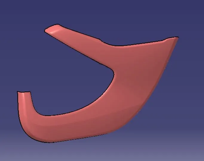
This Class A surface is made by using the JOIN Command and joining a no. of components from reference surface.
CLASS B SURFACE OF THE LOWER SUBSTRATE
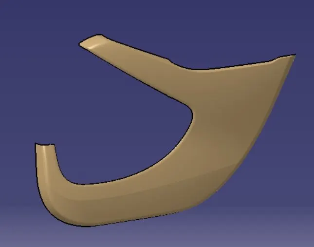
The Class B surface is same as the Class A surface but it should be at an offset of 2.5mm from the Class A surface.
FINAL TRIM OF LOWER SUBSTRATE WITH CLASS A, CLASS B, CLASS C SURFACE ALONG WITH TOOLING AXIS
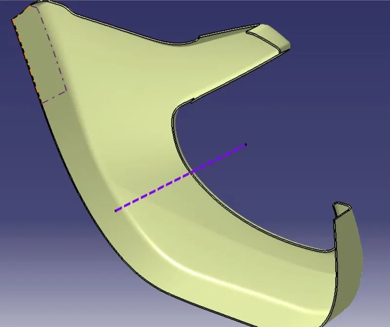
This final trim is made from joining or trimming Class A, Class B and Class C surfaces. Class C surfaces are made with reference to Class A surface using SWEEP and TRIM commands.
DRAFT ANALYSIS OF LOWER SUBSTRATE
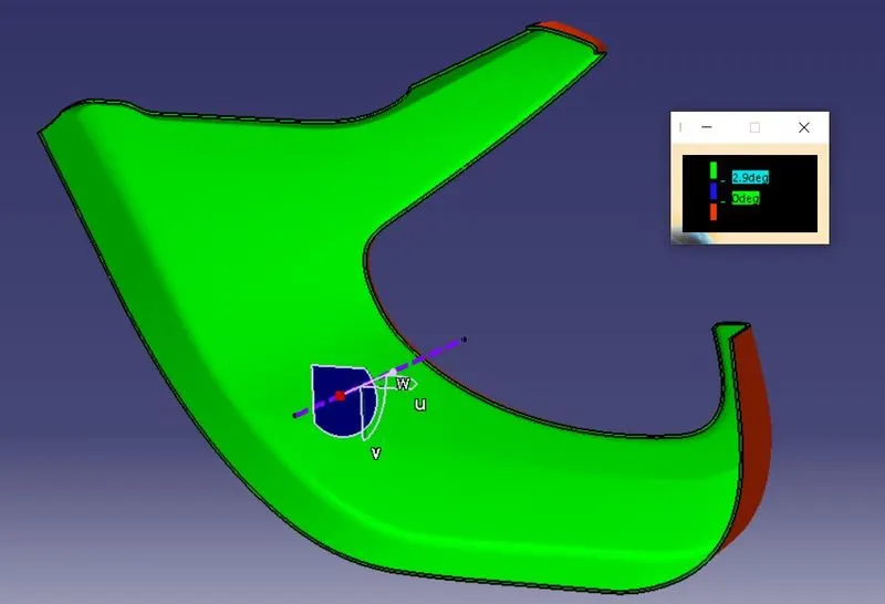
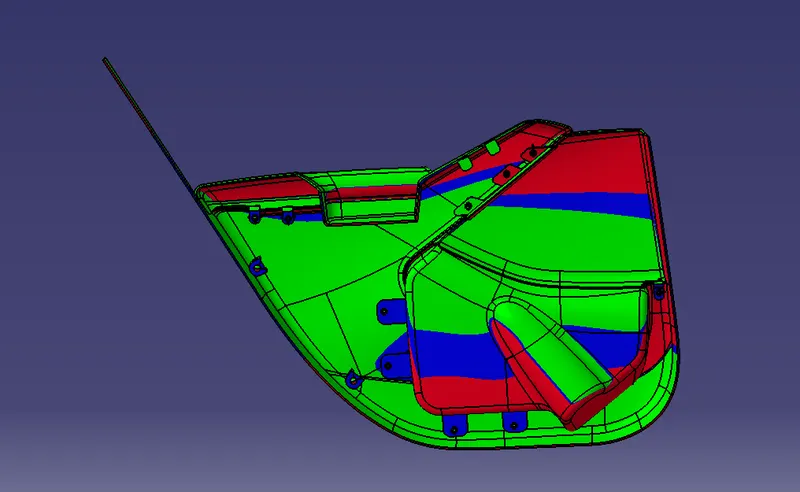
All areas are with minimum draft of 2.9deg except for a particular area shown in the next image.
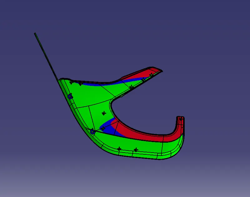
All dimensions are with a minimum draft angle of 0.45 deg along tooling axis of lower substrate.
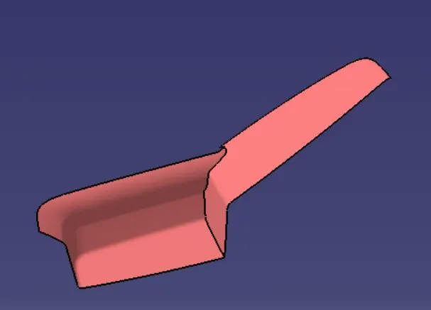
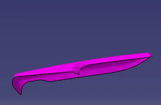
2. DOOR ARM REST
Arm rest is divided into two parts:
PART 1 AND PART 2 because the can only be produces with two tooling axis.
CLASS A SURFACE
PART 1
PART 2
CLASS B SURFACE
PART 1
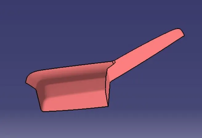
PART 2
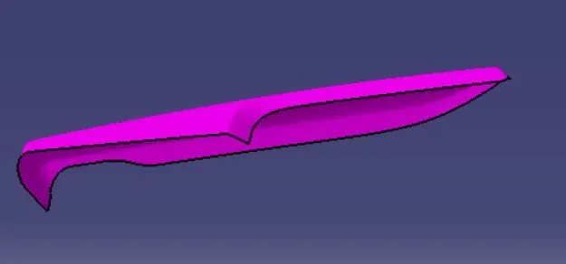
FINAL TRIM WITH TOOLING AXIS
PART 1
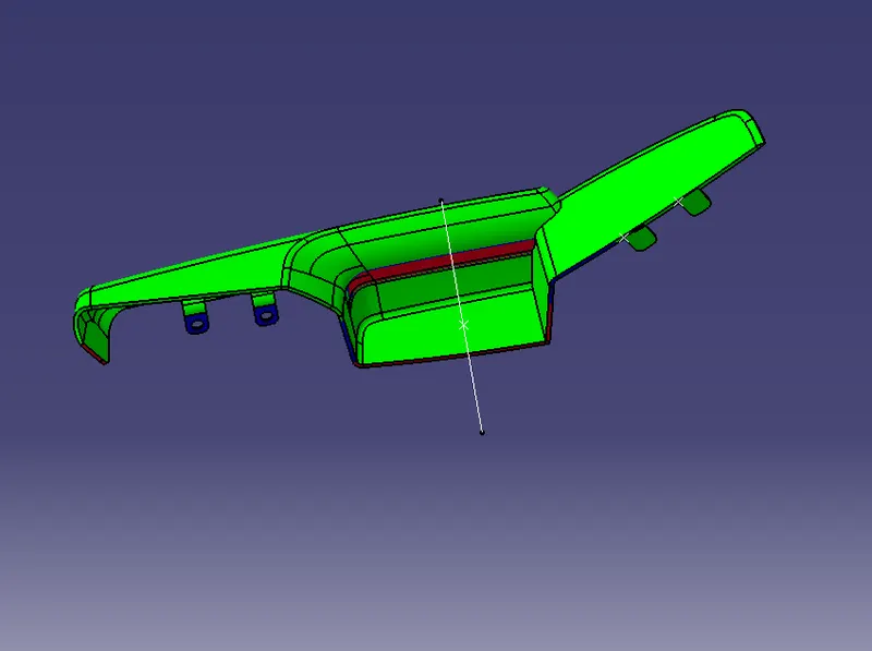
Part 1 of door arm rest with flanges and tooling axis
3. MAP POCKET
It also constitute of two components
CLASS A SURFACE
COMPONENT 1
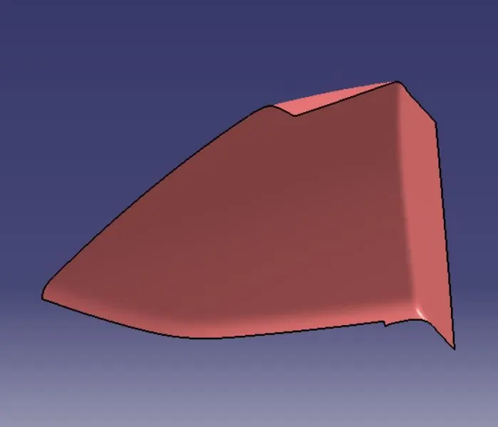
COMPONENT 2
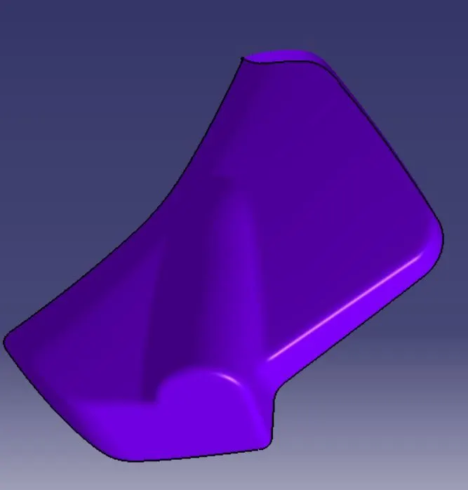
CLASS B
COMPONENT 1
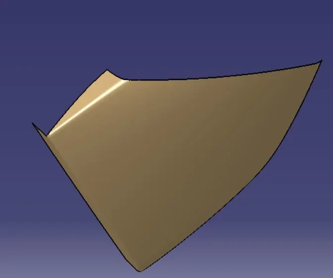
COMPONENT 2
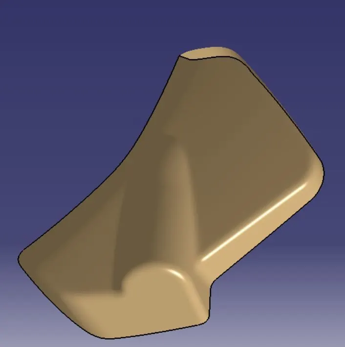
FINAL TRIM WITH TOOLING AXIS AND FLANGES
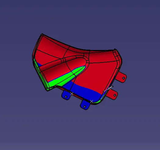
Minimum draft of 2.363deg. Minimum draft of 1.846deg.
DOOR TRIM PANEL
FINAL ASSEMBLY