Week - 4
AIM:
- Implement control logic of a washing machine using stateflow by giving certain condition as per power input and water input. As per this input ,machine operates and obtain output by lamp light.
- Create the stateflow for gear shift and vary the speed as input and obtain the ouput as the gear number in display.
OBJECTIVE:
- To Implement control logic of a “washing machine” using Stateflow as per given sequence:
- If the power supply is available, the system gets activated
- If the Water supply is not available, stop the process & indicate through LED
- Soaking time should be 200s followed by Washing time of 100s.
- Then rinsing happens for next 20s & dryer runs for 50s
After all the processes have completed turn on the finished LED
2. To make a Simulink chart for the “Gear shift” logic as per below conditions:
Speed Range(kmph) Gear
0 to 15 1
16 to 25 2
26 to 40 3
41 to 60 4
Above 61 5
Give speed input while the simulation is running & display the gear number.
SOFTWARE USED: Matlab, Simulink
STUDY-1:
WORKING OF WASHING MACHINE:
All the important parts of the clothes washer are electrically controlled, including the inner drum, the valves, the pump, and the heating element. The programmer is like the conductor of an orchestra, switching these things on and off in a sensible sequence that goes something like this:
- You put your clothes in the machine and detergent either in the machine itself or in a tray up above.
- You set the program you want and switch on the power.
- The programmer opens the water valves so hot and cold water enter the machine and fill up the outer and inner drums. The water usually enters at the top and trickles down through the detergent tray, washing any soap there into the machine.
- The programmer switches off the water valves.
- The thermostat measures the temperature of the incoming water. If it's too cold, the programmer switches on the heating element. This works just like an electric kettle or water boiler.
- When the water is hot enough, the programmer makes the inner drum rotate back and forth, sloshing the clothes through the soapy water.
- The detergent pulls the dirt from your clothes and traps it in the water.
- The programmer opens a valve so the water drains from both drums. Then it switches on the pump to help empty the water away.
- The programmer opens the water valves again so clean water enters the drums.
- The programmer makes the inner drum rotate back and forth so the clean water rinses the clothes. It empties both drums and repeats this process several times to get rid of all the soap.
- When the clothes are rinsed, the programmer makes the inner drum rotate at really high speed—around 80 mph (130 km/h). The clothes are flung against the outside edge of the inner drum, but the water they contain is small enough to pass through the drum's tiny holes into the outer drum. Spinning gets your clothes dry using the same idea as a centrifuge.
- The pump removes any remaining water from the outer drum and the wash cycle comes to an end.
- You take your clothes out and marvel at how clean they are!
- But there's still the problem of drying your wet clothes to figure out.
CONTROL LOGIC OF WASHING MACHINE AND EXPLANATION:
- To create this control system in simulink insert the chart and create the logic system using stateflow. The stateflow excute the flow of inputs "if" the condition is accept.
- In this control logic the input power is applied to ON the washing machine and the power supply is flow in other system. The conditions are applied to move other sequence of operation in stateflow.
- Water supply is execute when power is ON ,so entry and exit are assigned as value of 0 to 1. While the condition is not ok water supply stops and it will come back to its constant state.
- This process is applied for each flow and time of working in each operations are initiate by sec that are given in question.
- Stateflow of washing machine are created and they are shown below,
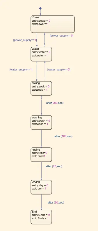
- Now assigned the input values of steadyflow and sequence of operation is initiate to identify the working division. Constant block is created to give an input power value of system.
- And other constant block is created for input of water supply and value as 1 to ON water and to run washing sequence.
- Display block is inserted with each sequence to display the results of operations.
- Lamp block is introduced to indicates wheather the operations are 'ON' or 'OFF' in different states.
RESULT:
STUDY-1:
Simulink Model are created and inputs are generated to power supply and water supply
- If the power supply and water supply are assigned as 0 value the ouput value of all operations become zero because no inputs are generated and conditions are not applied.
- Lamp is in red color due to 'OFF' of operation system. That are shown as below,
- In this state power supply is assigned as value 1 and water supply remains 0. The power are generated and that indicates as in display value 1 lamp is in green light. But the water supply is 0 so other operations are not proceed that value as 0 and lamp is in red light.
- Lamp color are indicates by user whether it may green,blue,red ,yellow,ect.
- Now the power supply and water supply value are assigned as 1. Power are generated from input and the operation starts , water supply also done by initiate the value of 1.
- Sequence of operation in stateflow starts when the condition is getting satisfied. Water supply is generated and other operations are followed by duration of time that we given in stateflow.
- Each operations are runned and results are obtained by display block. Lamp is turned "ON" and it indicates green color as result.