Week -2
1. To make a simulink model of Doorbell using solenoid block.
2. To Use a thermistor to sense the temperature of a heater & turn on or turn off the fan as per below conditions.
Given Inputs: Temperature source: 20 °C from 0 to 10 seconds, 27 °C from 10 to 30 seconds, 23 °C from 30 to 50 seconds
Fan conditions: ON if the temperature above 25 °C, OFF otherwise.
OBJECTIVE :
1. Create a Simulink model of Doorbell using Solenoid Block. Operate the Door bell Simulink model system and plot the results.
2. Using a thermistor to sense the temperature of a heater & turn on or turn off the fan as per given conditions.Run the Simulink Model as per given conditions and plot the results.
EXPLANATION :
STUDY - 1 :
Make a simulink model of Doorbell using solenoid block
Making a Simulink model of Doorbell using solenoid block by using below parameters.
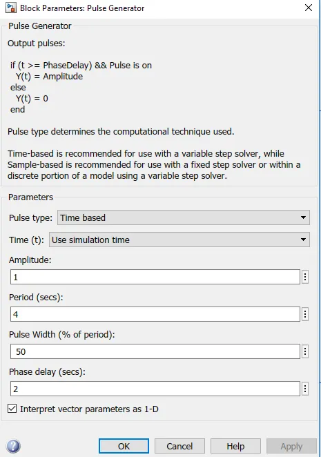
Pulse Generator (Input):
The Pulse Generator block generates square wave pulses at regular intervals. The block waveform parameters, Amplitude, Pulse Width, Period, and Phase delay, determine the shape of the output waveform. The following diagram shows how each parameter affects the waveform.
Switch :
The Switch block models a switch controlled by an external physical signal.
If the external physical signal PS is greater than the value specified in the Threshold parameter, then the switch is closed, otherwise the switch is open.
Battery:
In Battery positive terminal is connected with Switch and negative terminal is connected with electrical reference.
Solenoid Block:
Solenoid block is connected with Switch & Battery and electrical circuit will be formed.
The Solenoid block represents the electrical characteristics and generated force for the solenoid in the following figure:
The return spring is optional. To remove the effects of this spring from the model, set the Spring constant parameter to 0.
To show the direction in which the solenoid acts, the block icon changes dynamically based on value of the Motion direction under excitation parameter.
Port C is connected with Mechanical Translational reference.
Ideal Translational Motion Sensor:
Ideal Translational motion sensor is connected with Solenoid block R to Observe the physical ,movement of the plunger.
Connections R and C are mechanical translational conserving ports that connect the block to the nodes whose motion is being monitored. Connections V and P are physical signal output ports for velocity and position, respectively.
The block positive direction is from port R to port C. This means that the velocity is measured as v = vR – vC, where vR, vC are the absolute velocities at ports R and C, respectively.
Port C is connected with Mechanical Translational Reference.
Scope:
Scope is connected with Ideal Translational Motion Sensor to get the Output. Ideal Translational Motion Sensor is used to convert physical signal into simulink model.
Solver Configuration:
Each physical network represented by a connected Simscape block diagram requires solver settings information for simulation. The Solver Configuration block specifies the solver parameters that your model needs before you can begin simulation.
SIMULINK MODEL :
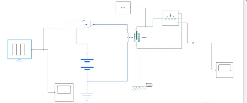
INPUT:
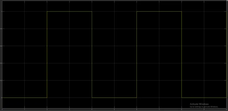
OUTPUT:
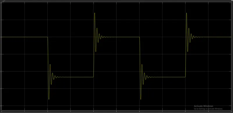
In the above arrangement, giving input as time period - 2 secs in the Pulse generator to open and close the switch. When the switch is closed the Solenoid block receives electrical power from the battery and plunger moves from port R to port C to hit the bell and producing sound.
Physical movement of the Plunger is observed by using Ideal Translational motion sensor and physical output is converted into simulink output model is displayed in the scope.By reducing the spring constant value and increasing the damping value vibrations will be reduced.
STUDY - 2 :
Using a thermistor to sense the temperature of a heater & turn on or turn off the fan as per given conditions.
Signal Builder(Input):
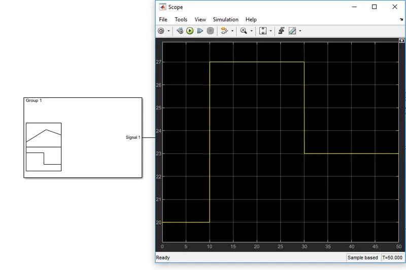
In Signal Builder, giving input values as per the given conditions.
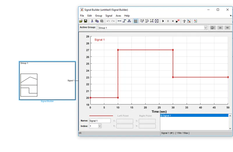
Given Inputs:
At Point1 - Time 0 sec - Temperature - 293K,
At Point2 - Time 10 secs - Temperature - 293K,
At Point3 - Time 10 sec - Temperature - 300K,
At Point4 - Time 30 sec - Temperature - 300K,
At Point5 - Time 30 sec - Temperature - 296K,
At Point6 - Time 50 sec - Temperature - 296K.
Controlled Temperature Source:
The Controlled Temperature Source block represents an ideal source of thermal energy that is powerful enough to maintain specified temperature difference across the source regardless of the heat flow consumed by the system.
Connections Aand B are thermal conserving ports corresponding to the source inlet and outlet, respectively. Port S is a physical signal port, through which the control signal that drives the source is applied.
Thermistor:
A thermistor is a type of resistor whose resistance is dependent on temperature, more so than in standard resistors. The word is a combination of thermal and resistor.
The Thermistor block represents an NTC thermistor using the B-parameter equation.
NTC - Negative Temperature Co-efficient
Resistor:
The Resistor block models a linear resistor, described with the following equation:
V=I·R
Where,
V - Voltage,
I - Current,
R - Resistance
Voltage Sensor:
The Voltage Sensor block represents an ideal voltage sensor, that is, a device that converts voltage measured between two points of an electrical circuit into a physical signal proportional to the voltage.
Voltage Source:
The Voltage Source block implements a voltage source with DC, AC, and noise components.
Electrical Reference:
The Electrical Reference block represents an electrical ground. Electrical conserving ports of all the blocks that are directly connected to ground must be connected to an ElectricalReference block. A model with electrical elements must contain at least one Electrical Reference block.
SIMULINK MODEL :
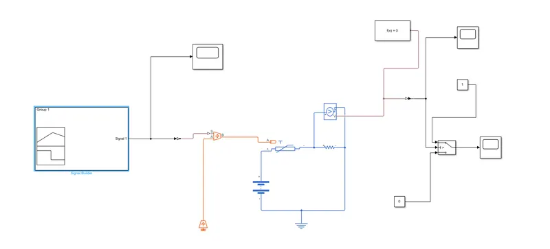
EXPLANATION OF MODEL:
Inputs are given to the Signal Builder and Connected with Temperature Controlled Source for maintaining the specified temperature difference across the source.Then input temperature flows through thermistor.
Thermistor is connected with Resistor, ensure that thermistor connected with positive terminal of the resistor and the voltage across the resistor is given by V(+) – V(–), and the sign of the current is positive when flowing through the device from the positive to the negative terminal. This convention ensures that the power absorbed by a resistor is always positive.Connect the Positive terminal of Voltage Source to positive terminal of the thermistor and connect the negative terminal of Voltage Source to negative terminal of Voltage sensor and Resistor to get the values from the Voltage sensor(like series connection) .
Output terminal of the voltage sensor is connected with Switch.Using the Switch Parameter for giving the condition as Fan must be ON if the temperature above 25 °C, OFF otherwise. Output is Successfully executed by connecting with scope as per the given condition.
INPUT:
OUTPUT:
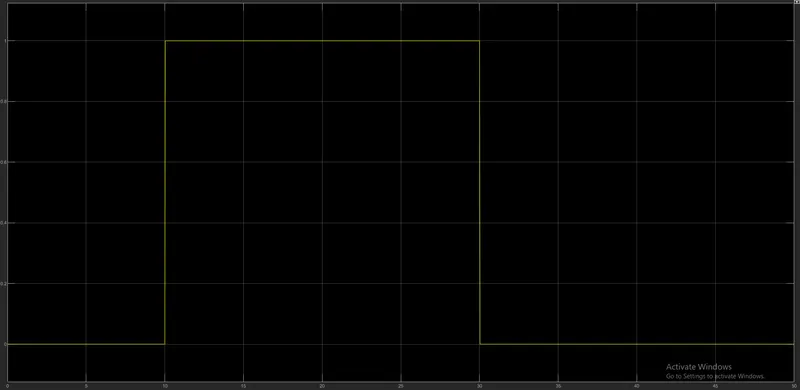
For 0-10 secs fan is in OFF condition, because temperature is 293K which is below 298K. After 10 secs temperature goes to 300K, so fan will turn ON, because temperature exceeds 298K. After 30 secs fan will turn OFF because temperature goes to 296K which is below 298K.
From the above results the given condition has been acheived and succesfully executed.