Week 11 - Final project
Aim:
* Creation of CAD model considering following inputs as like in OEM and tier1 companies
- a) Class A surface
- b) Nominal thickness
- c) Attachment features
* Find a attachment strategy for the door panel complete work.
* Use Push pin with Dog house for Lower substrate – Door panel attachment
* Use heat stakes for part to part attachment.
Procedure:
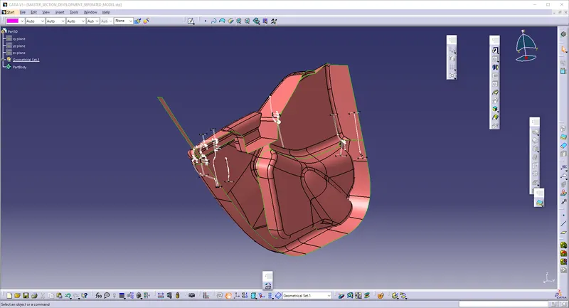
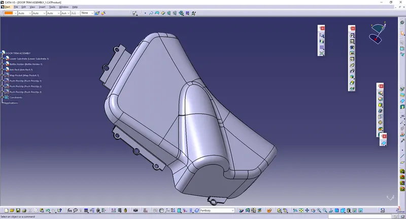
* The CAT file is downloaded and it is obtained like this.
* Go to ASSEMBLY WORKBENCH and give PART and assign the surface which are separated.
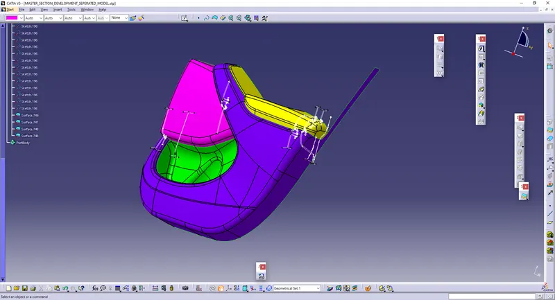
The Separated surfaces are to be named as:
i) Map Pocket
ii) Bottle holder
iii) Lower Substrate
iv) Arm Rest.
* These are the class-A surfaces, and which are to be made into class-b and class-c surfaces.
Doing Procedure:
i) Door Armrest:
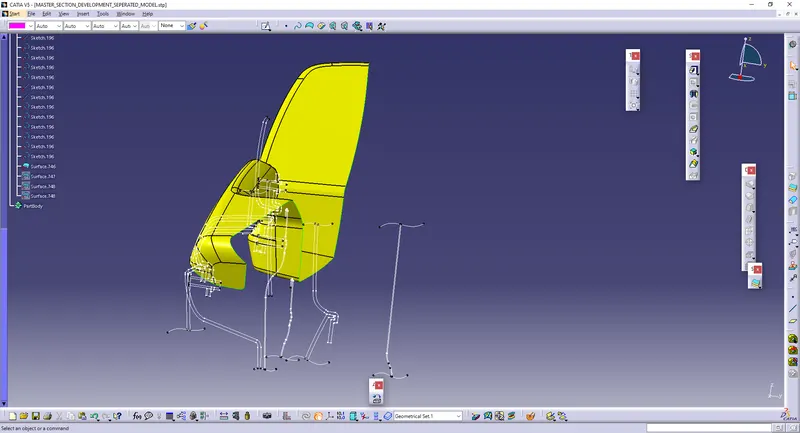
* This is a Class-A Surface which is given.
* Offset the Surface to 2.5 mm.
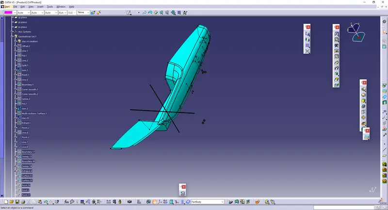
* Some Parts of the surfaces cannot come with some surfaces. So, in order to Fill the gap, Create the Boundary and using the Edges of the surface and boundary lines as reference, create the MULTI-SECTION SOLID and JOIN them together.
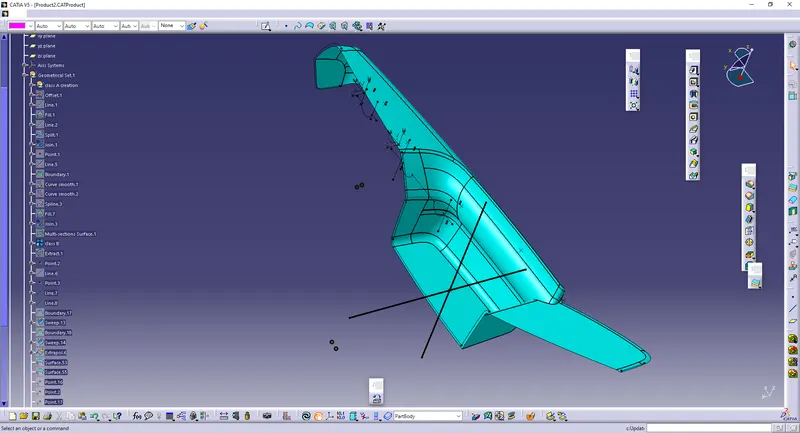
* Create the C-Surface By creating the boundaries using Sweep option.
* If some of the surfaces are not created, create the Multi-section surfaces and Join them together.
* Trim the Class A-and-C surfaces with class-B surface.
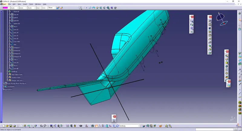
* Make sure that there should be no boundary gaps in the A and C surface.
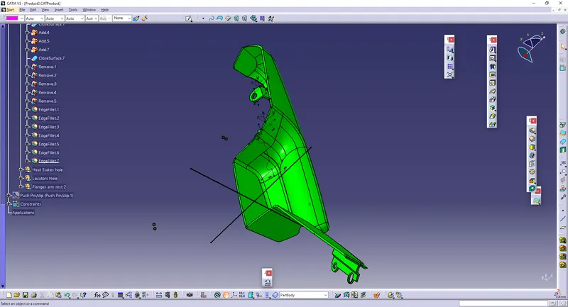
* Go To Part-Design, and Change the surface into a part.
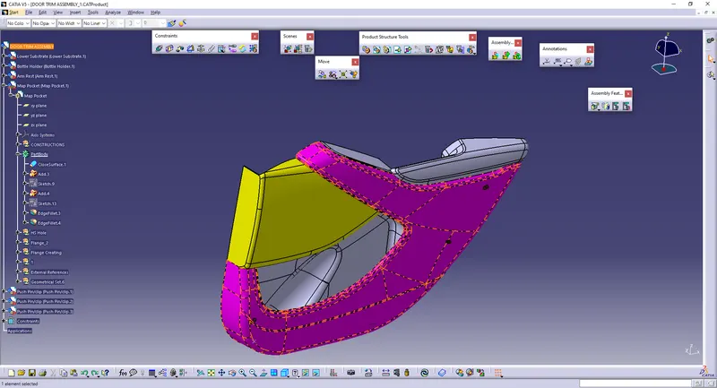
ii) Map Pocket:
* This is a Class-A Surface which is given.
* Offset the Surface to 2.5 mm.
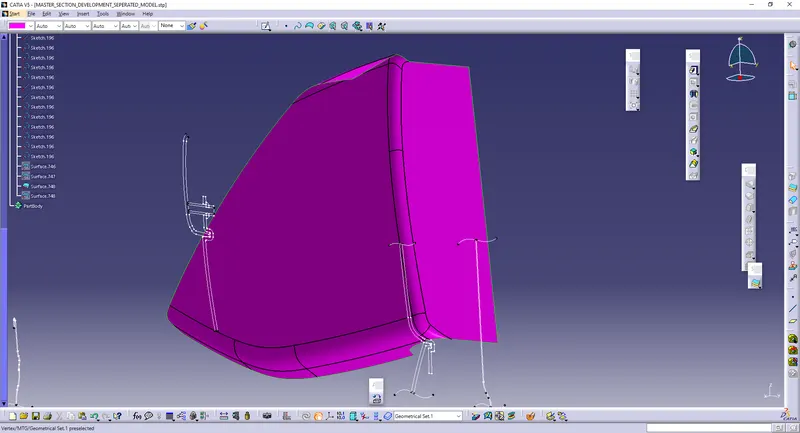
* Some Parts of the surfaces cannot come with some surfaces. So, in order to Fill the gap, Create the Boundary and using the Edges of the surface and boundary lines as reference, create the MULTI-SECTION SOLID and JOIN them together.
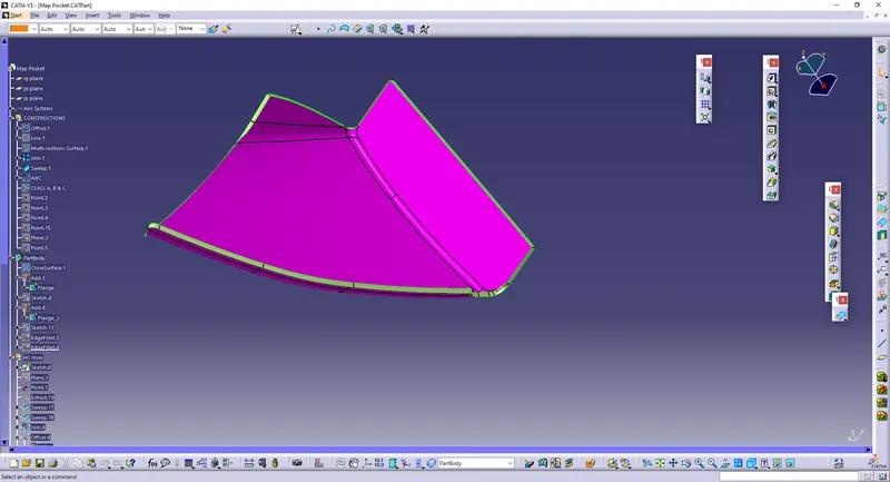
* Create the C-Surface By creating the boundaries using Sweep option.
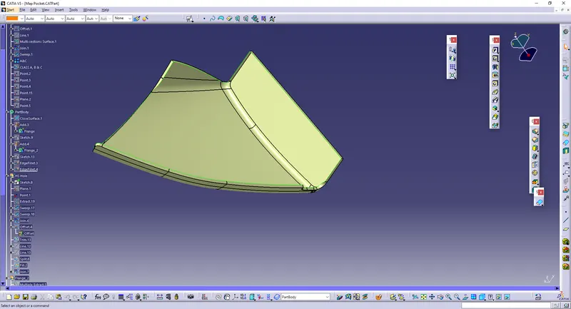
* If some of the surfaces are not created, create the Multi-section surfaces and Join them together.
* Trim the Class A-and-C surfaces with class-B surface.
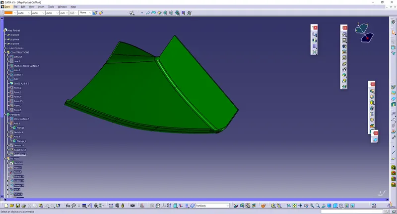
* Make sure that there should be no boundary gaps in the A and C surface.
* Go To Part-Design, and Change the surface into a part.
iii) Bottle Holder:
* This is a Class-A Surface which is given.
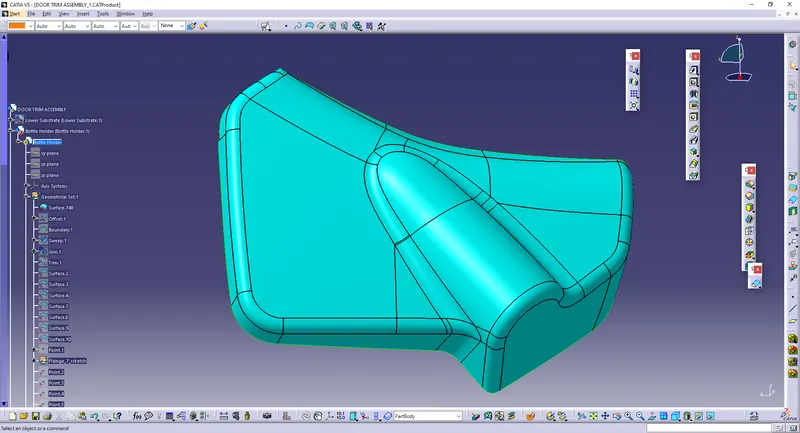
* Offset the Surface to 2.5 mm.
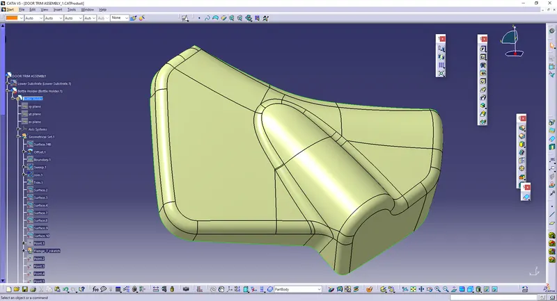
* Some Parts of the surfaces cannot come with some surfaces. So, in order to Fill the gap, Create the Boundary and using the Edges of the surface and boundary lines as reference, create the MULTI-SECTION SOLID and JOIN them together.
* Create the C-Surface By creating the boundaries using Sweep option.
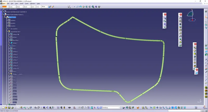
* If some of the surfaces are not created, create the Multi-section surfaces and Join them together.
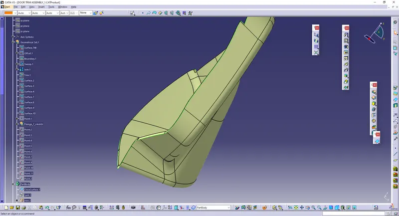
* Trim the Class A-and-C surfaces with class-B surface.
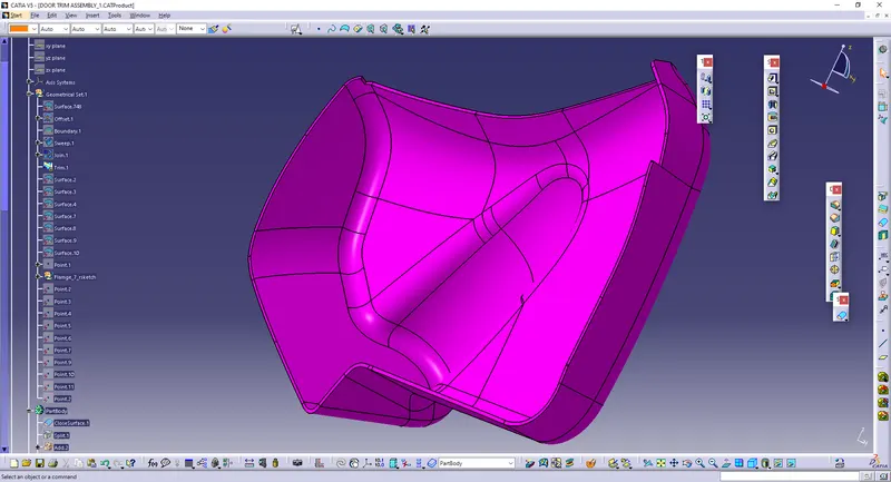
* Make sure that there should be no boundary gaps in the A and C surface.
* Go To Part-Design, and Change the surface into a part.
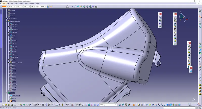
iv) Lower Substrate:
* This is a Class-A Surface which is given.
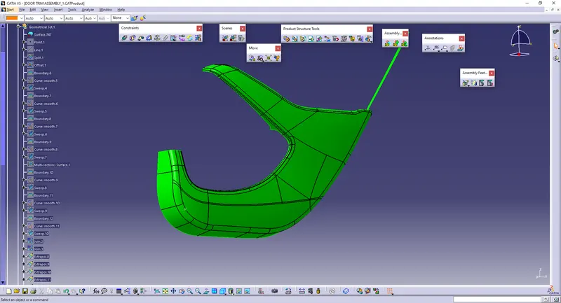
* Then, Draw the line by creating the point to split the excess surface in the LOWER SUBSTRATE region.
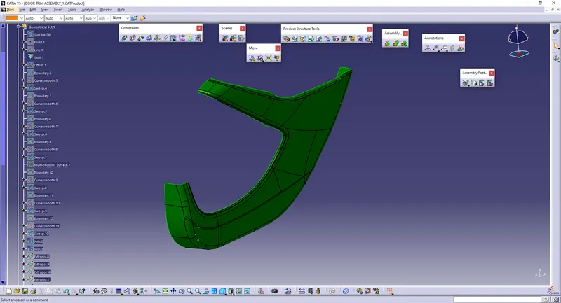
* Offset the Surface to 2.5 mm.
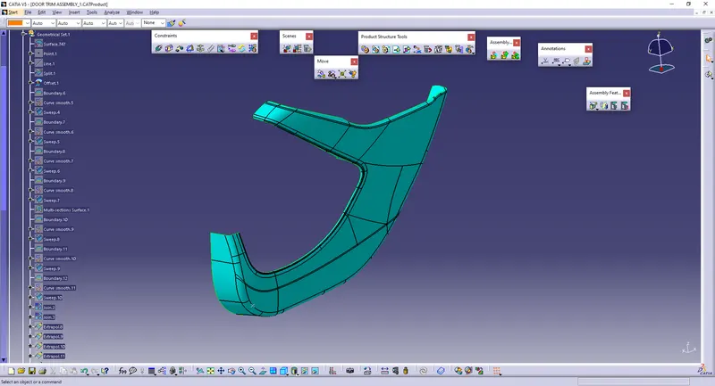
* Some Parts of the surfaces cannot come with some surfaces. So, in order to Fill the gap, Create the Boundary and using the Edges of the surface and boundary lines as reference, create the MULTI-SECTION SOLID and JOIN them together.
* Create the C-Surface By creating the boundaries using Sweep option.
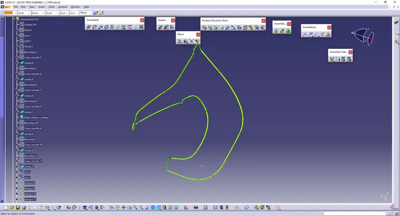
* If some of the surfaces are not created, create the Multi-section surfaces and Join them together.
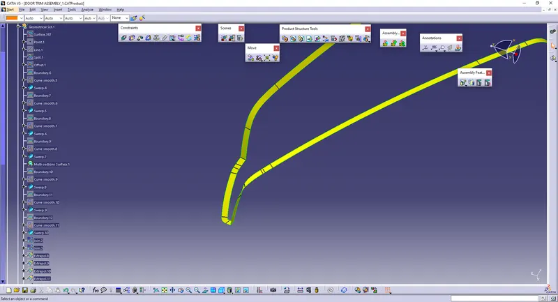
* Trim the Class A-and-C surfaces with class-B surface.
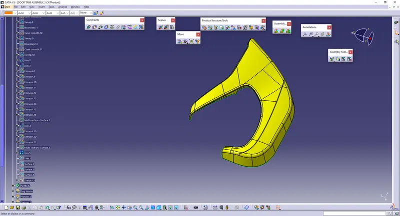
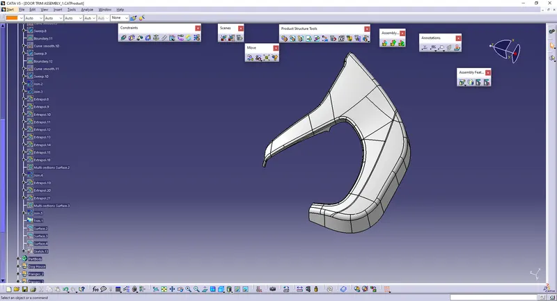
* Make sure that there should be no boundary gaps in the A and C surface.
* Go To Part-Design, and Change the surface into a part.
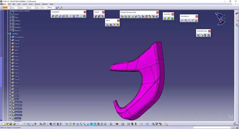
Creation Of Flanges:
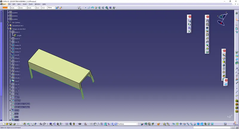
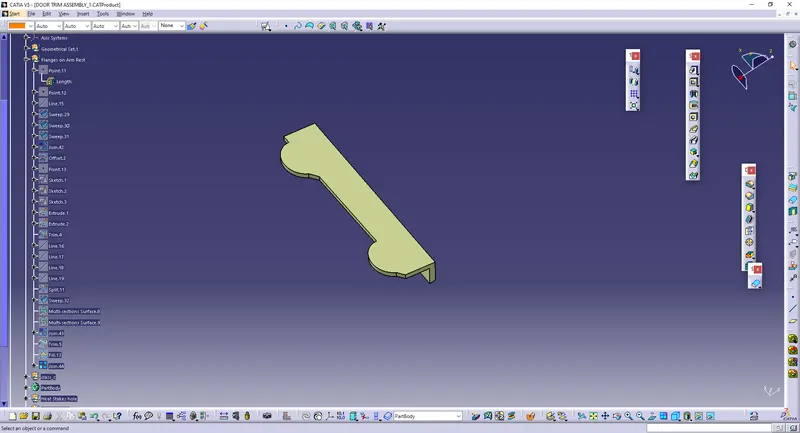
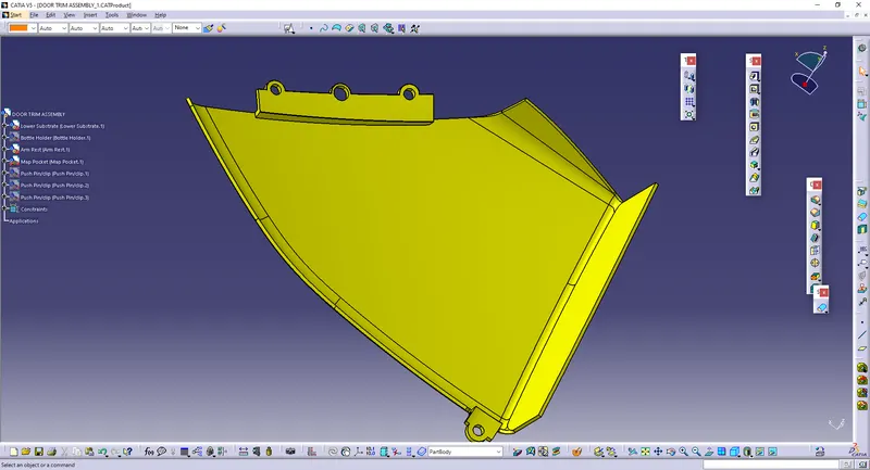
* Using the Master section as reference and the section is to be extracted, only for few portions.
* Using the extracted surface, and the anothe extract is also to be done in the edges.
* Then, Use SWEEP and create the Sweep surface as the taking the reference surface and the extracted edge on the edges of the surface.
* Create the Sweep on the edges of the surfaces and use the Reference surface and then create the another surface
* Join those surfaces and Offset it into 3 mm
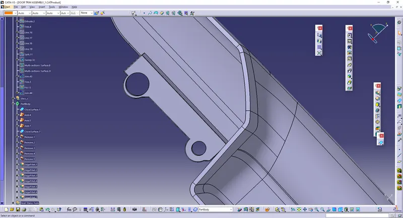
* Draw the line and extrude it. Make sure that the lines are used in separate sketches.
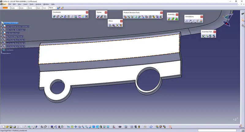
* Draw the Circle to bring the circular column.
* Join them together and convert it into the part Body.
* Create the another body to draw the cylinder and Remove using Boolean operation.
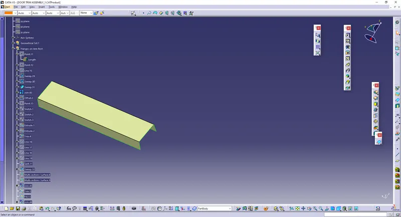
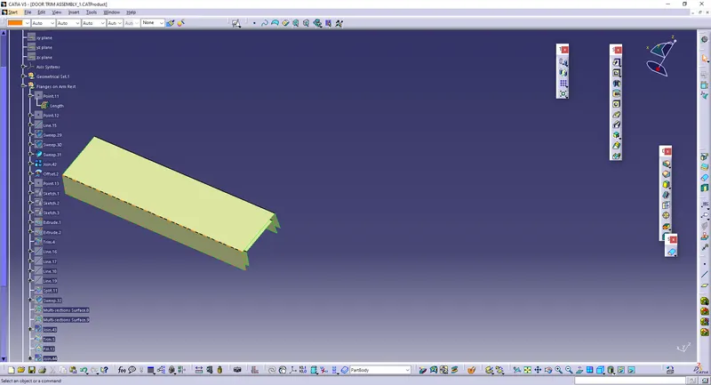
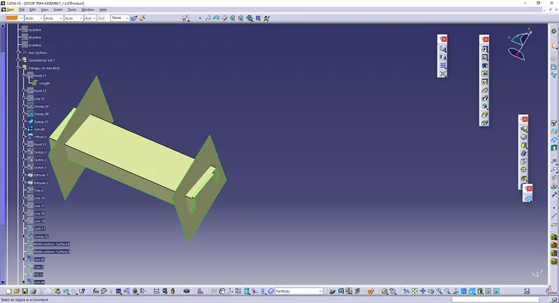
Creation Of Heat-stakes and Locators:
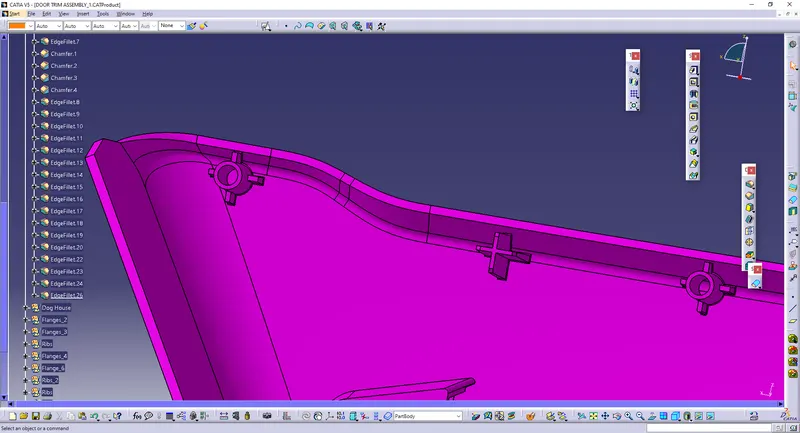
* The Points are created in the middle of the holes in the flanges.
* In one place, we need to draw the circle on the middle of the point, that diameter is to be lower than the hole in the flanges.
* Pad the circle to bring it as solid.
* In order to create the locators, Draw the cross lines, of each 10 mm, then pad it by using NEUTRAL FIBER.
* In order to create many, Use TRANSLATE to move the part.
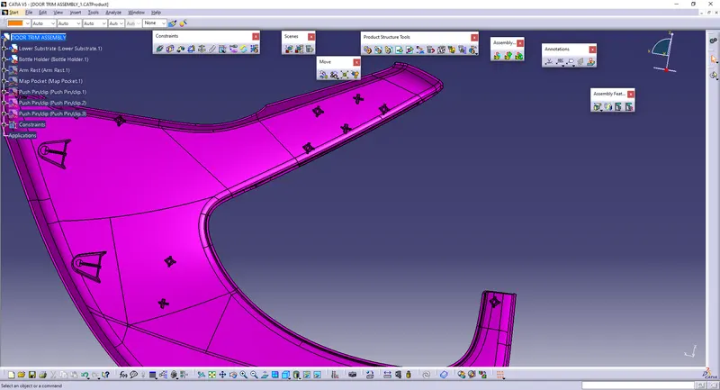
* Copy the body, and give Paste Special into the same part and thus, the same component copy exists.
* Hide the original component and use TRANSLATE>>Point-to-point and select the another point as destination, thus the multiple heat stakes and locators are created.
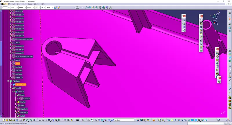
Creation Of Doghouse:
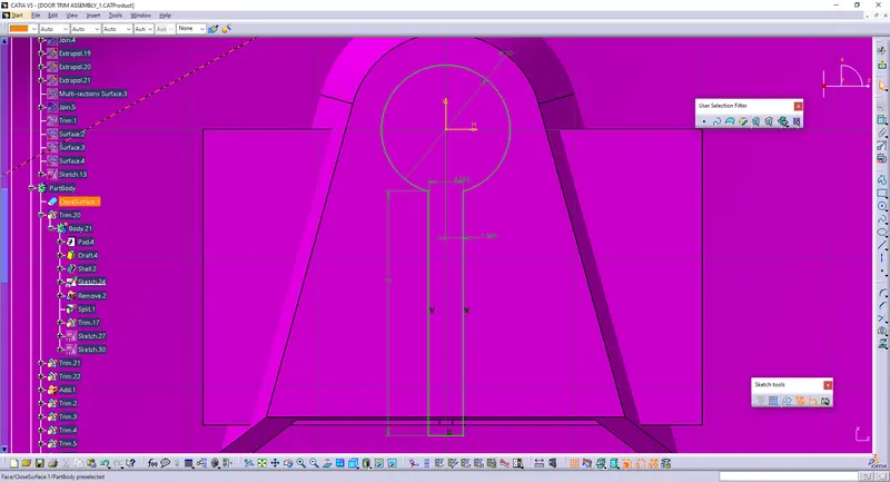
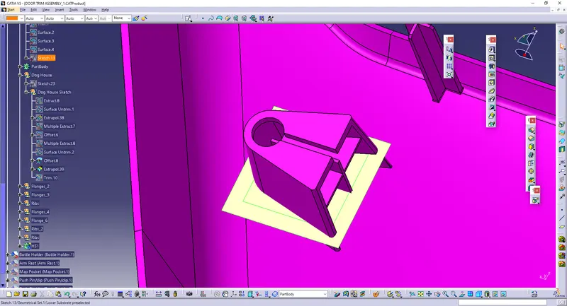
* Create the Sketch from the Top View
* Pad it till the Bottom
* Draw the Keyhole and Remove the Part and so the Keyhole is made.
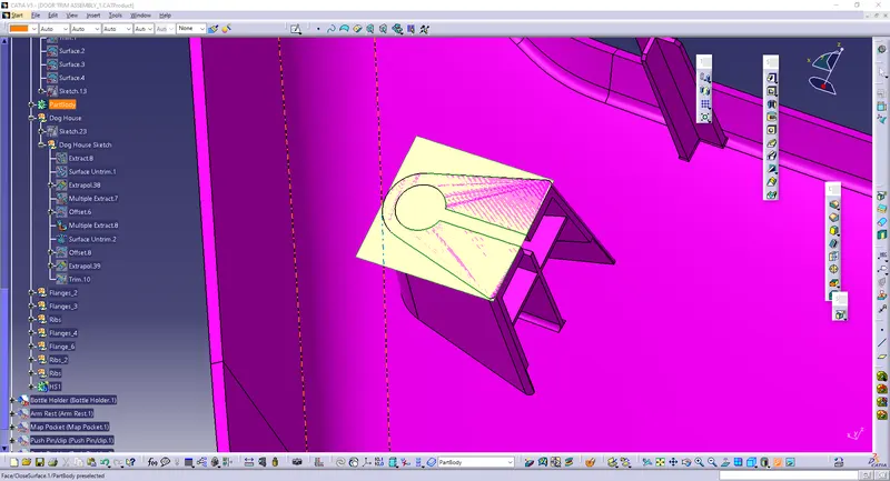
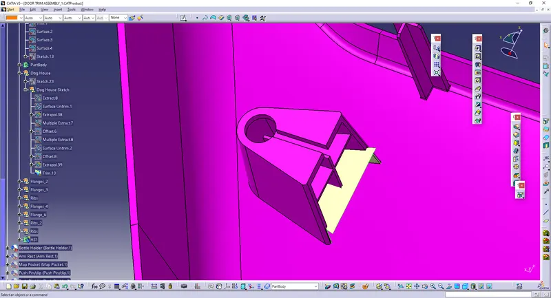
* Extract and untrim the top portion and offset the surface, which is to be 3mm above the bottom, and Extract the side-walls and offset to 1.5mm and extrapolate the offset surface for easy trim.
* Go to part body and split the cored surface.
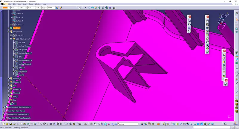
* And Hence the coring is made.
* Use the Front part of the doghouse created and make the ribs.
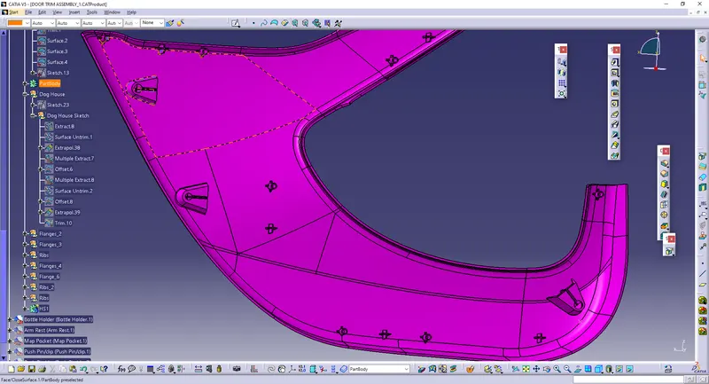
* In order to create many, Use TRANSLATE to move the part.
* Copy the body, and give Paste Special into the same part and thus, the same component copy exists.
* Hide the original component and use TRANSLATE>>Point-to-point and select the another point as destination, thus the multiple Dog-houses are created.
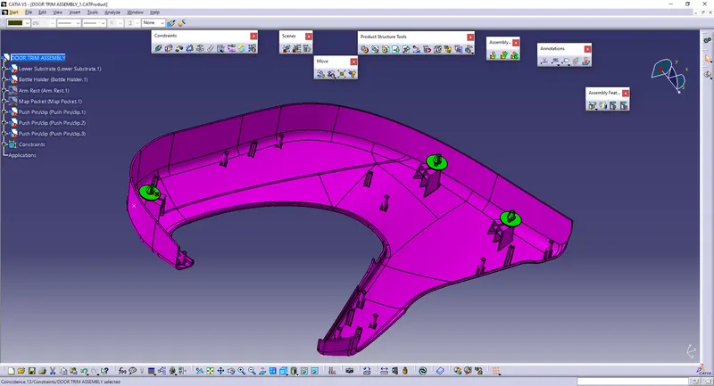
Assembly of Push-Clip:
* Go to Assembly part and open the Existing Component and select the Push-pin.
* The Push Pin will be on the work-bench and Give Contact constraints with respect to planes.
* Then, manipulate it according to the position in the top of the Doghouse.
* Copy the Part and paste the part in the product and repeat the process for clipping in the doghouses.
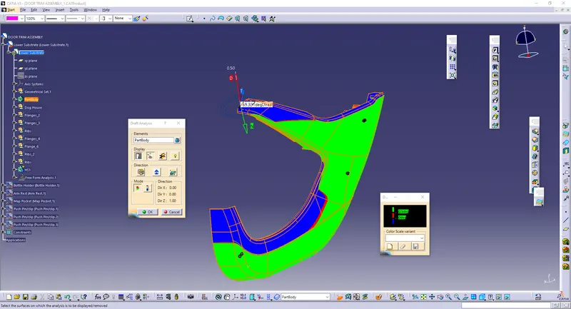
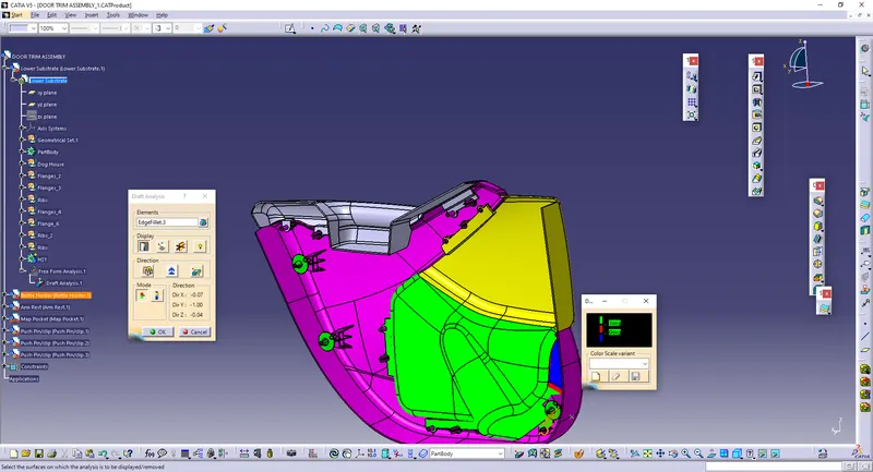
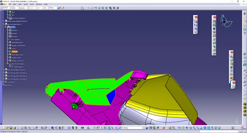
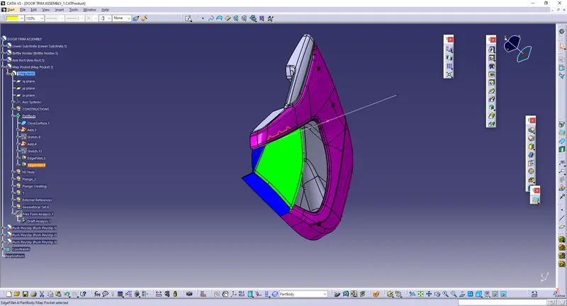
Draft-Analysis: