Week 11 - Final project
AIM:
- To design and development of vehicle interior door trim using Catia V5 with given class A surface along with Master section. Also create the side attachment features as per design rules.
Objective:
- To create the thickened part using master section for reference.
- To create the mounting features as per design guidelines in the industry and with master sections.
- To perform draft analysis and tooling analysis.
Introduction:
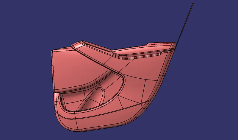
The door panel is the interface between the interior of the car and inner working of the door. Generally, the door panel is divided in to parts for easy designing like arm rest map pocket lower substrate. These require one of the toughest requirements among the interior parts of the car. This should be designed to with stand the load while being less than 2mm in thickness and also to protect the occupants during collisions.
Method followed in creation of the plastic new product design are:
- Tooling axis creation
- Class B surface creation
- Class C surface creation
- Closed body creation
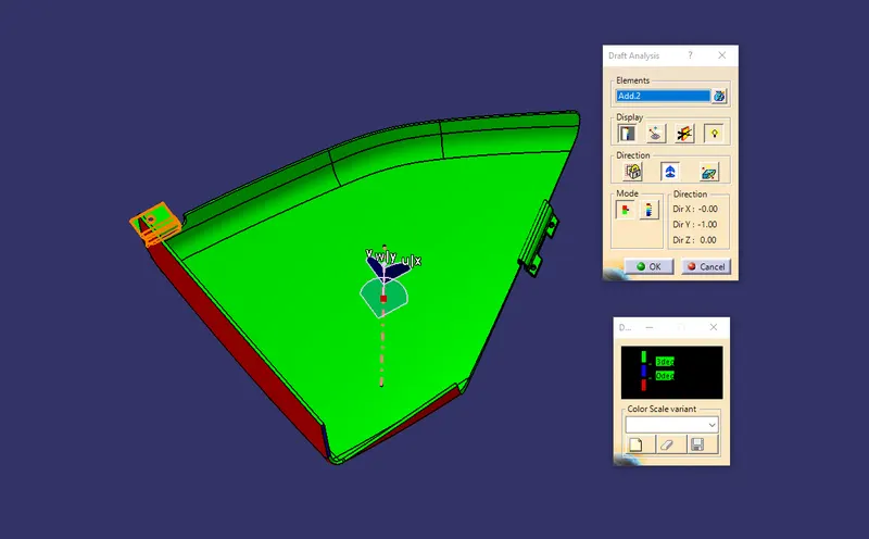
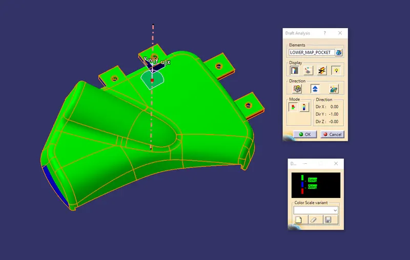
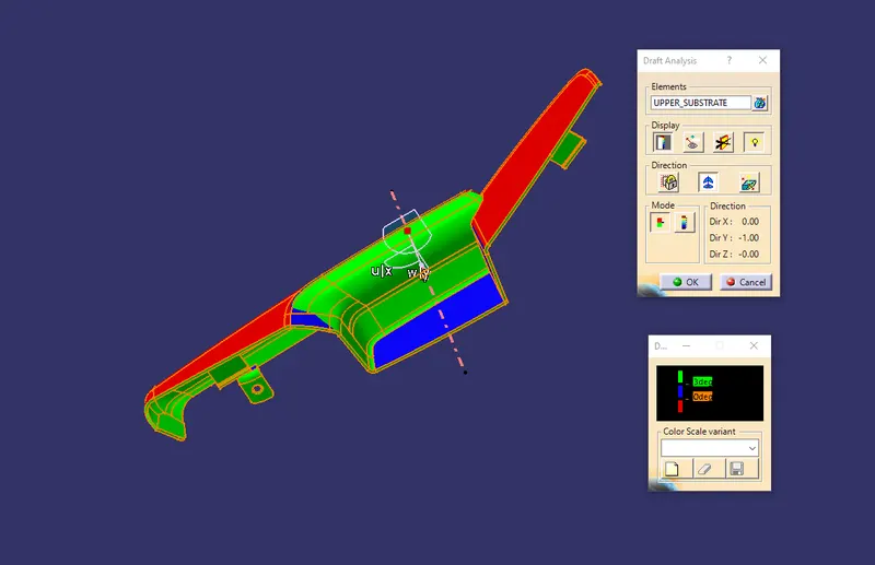
- Draft analysis
Procedure of part creation:
Interior door trim consists of four components.
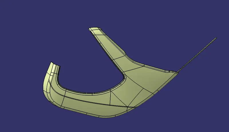
- Lower substrate
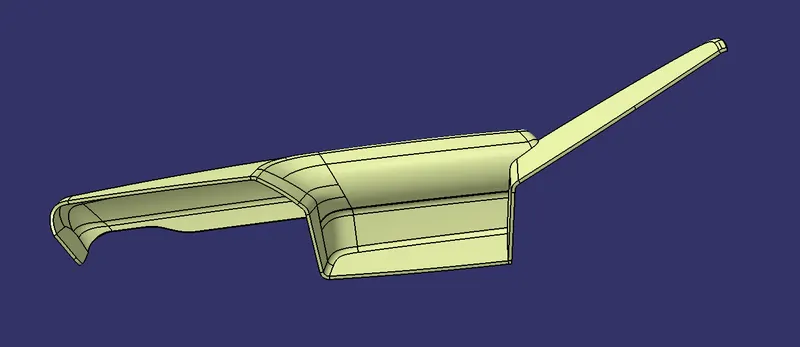
- Upper substrate
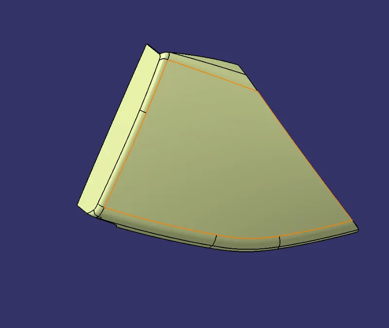
- Upper Map pocket
- Lower map pocket
Given data:
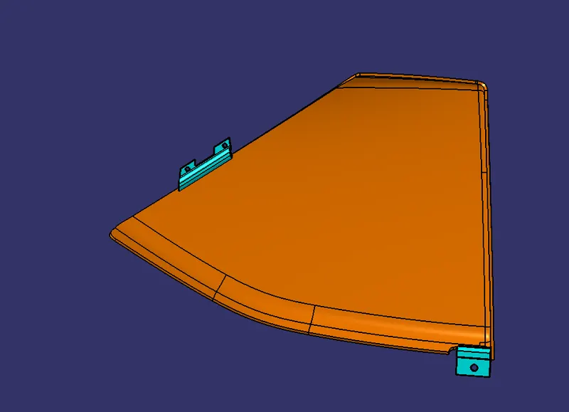
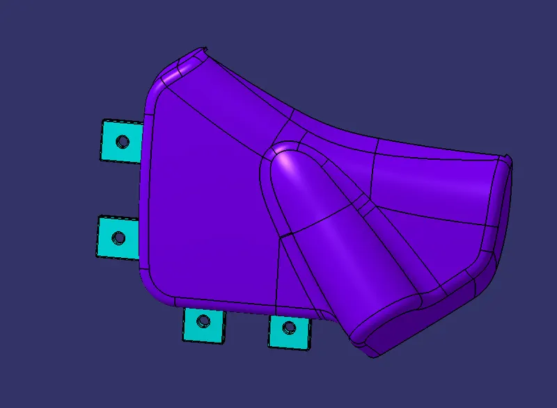
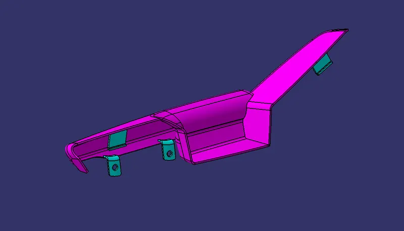
Class A surface of all parts of door trim:
- In automotive design a Class A surface in any of a set of free form surfaces of high efficiency and quality. Although strictly its nothing more than saying the surfaces have curvature and tangency alignment to ideal aesthetical reflection quality, many people interpret class A surface to have G2 or even G3 curvature continuity to one another. Class A surfacing is done using computer aided digital applications. Class A surface modellers are also called digital sculptors in the industry.
Lower Substrate:
Upper Substrate:
Upper map pocket:
Lower map pocket:
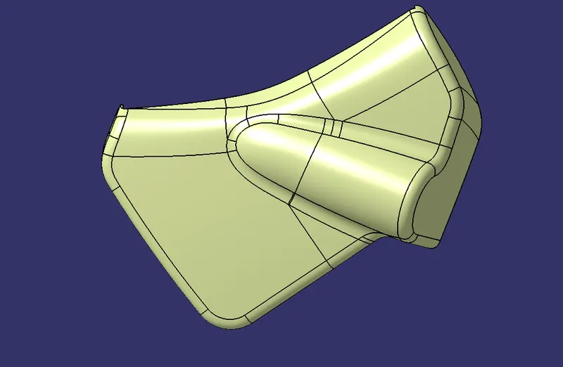
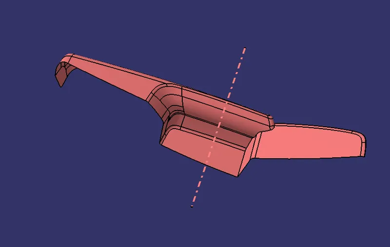
Tooling Axis:
- Tooling axis is nothing but the direction in which the core and cavity opens and closes Design engineer works on it to analyse the Class A surface and finds out the best possible tooling direction keeping in mind all the draft angle is with respect to the tooling axis so that the component can be easily ejected from the moulds.
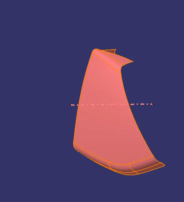
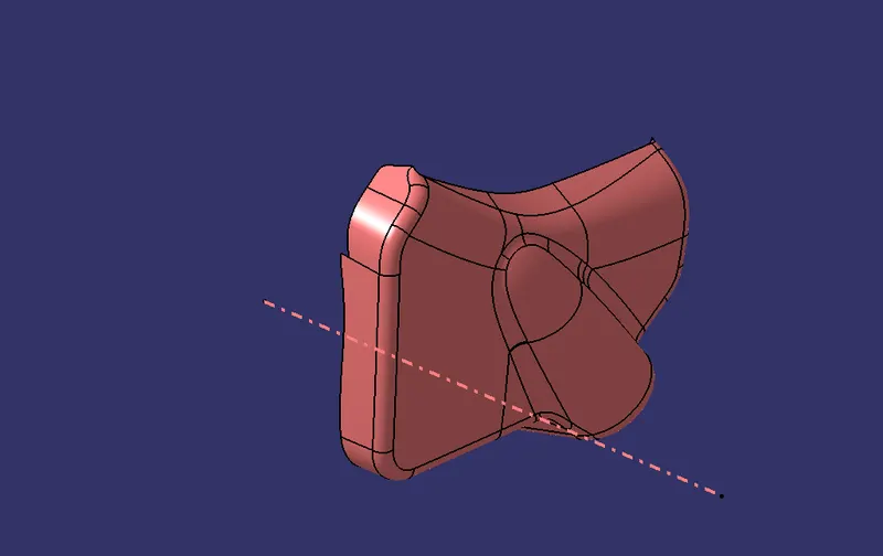
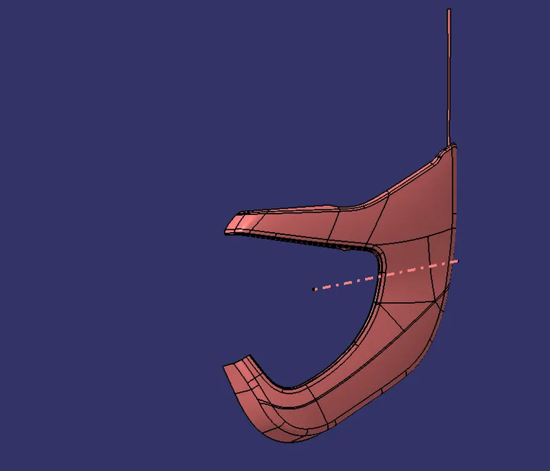
Draft analysis of class A surface:
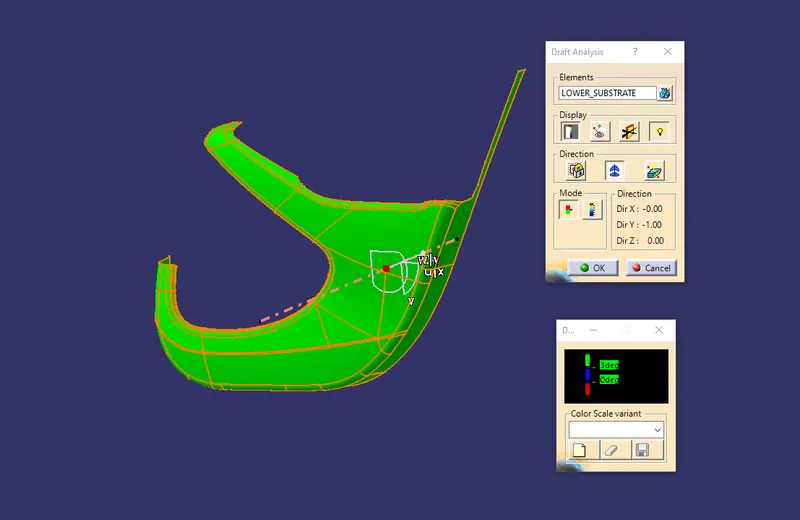
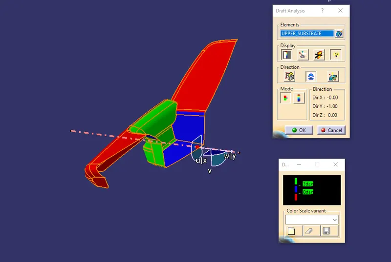
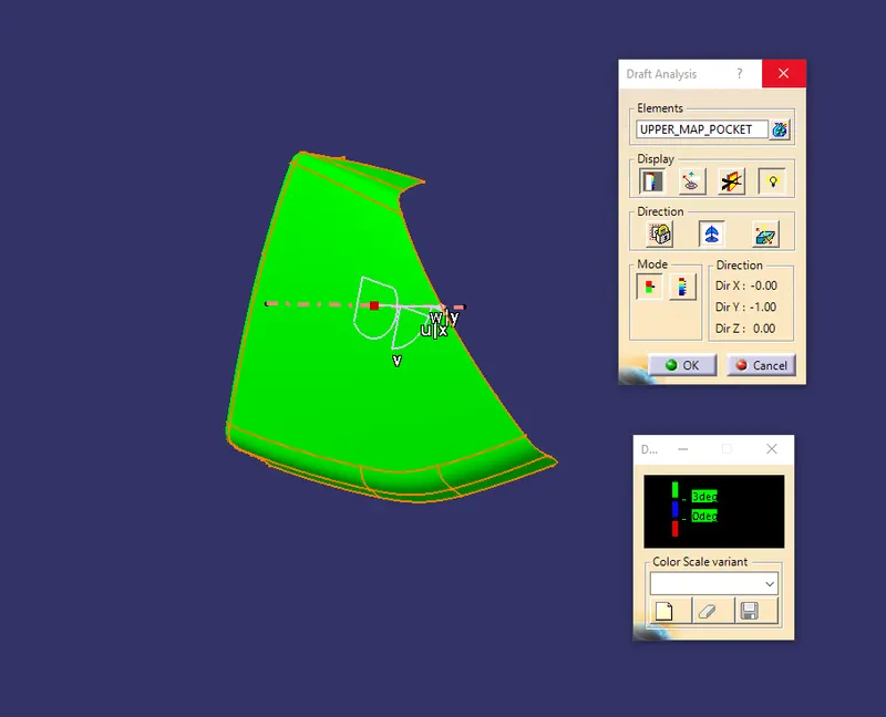
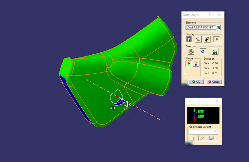
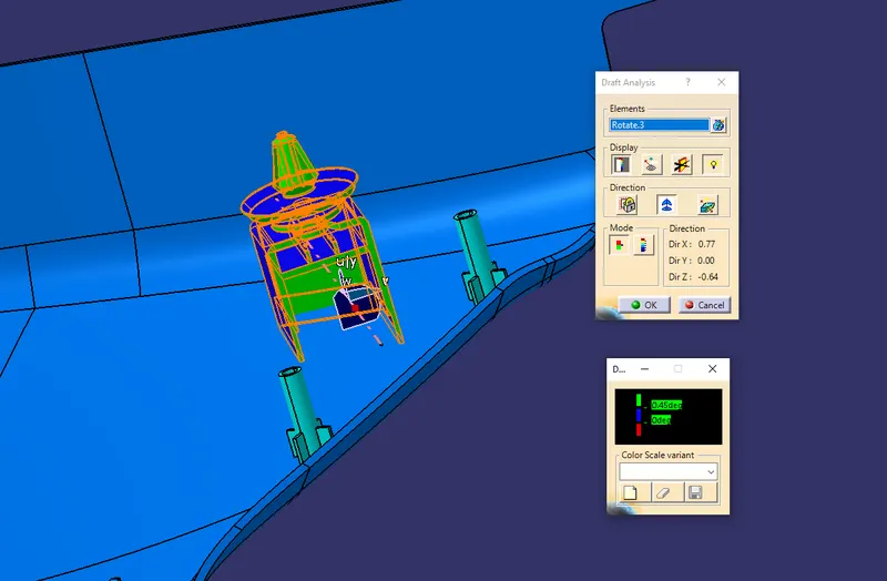
- The draft analysis command enables you to detect if the part you drafted will be easily removed. This type of analysis is based on colour ranges identifying zones on the analysed element where the deviation from the draft direction at any point, corresponds to specified value.
Class B surface creation:
- Class B surface includes derived surfaces created by offset operations from class A surfaces to define the thickness of the material. In this file it is important to link Class B surfaces geometrically to enable an adaptation to class A surfaces.
- After creation the tooling axis B surface is to be created which is nothing but the surface parallel to the A surface B surface contains all the fillets and the edges which the A surface contains.
Class C surface creation:
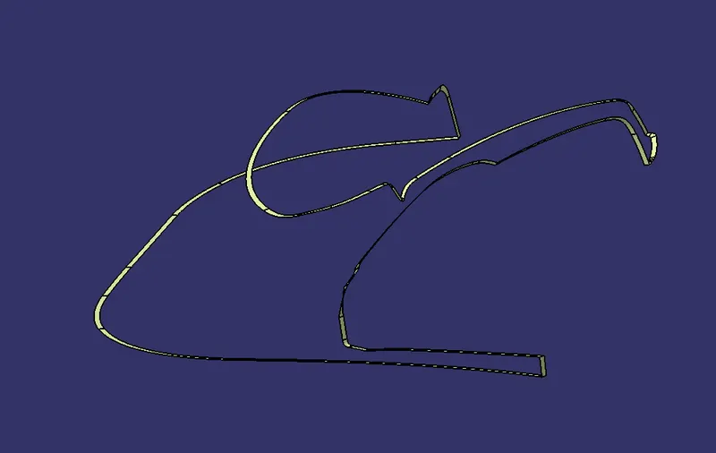
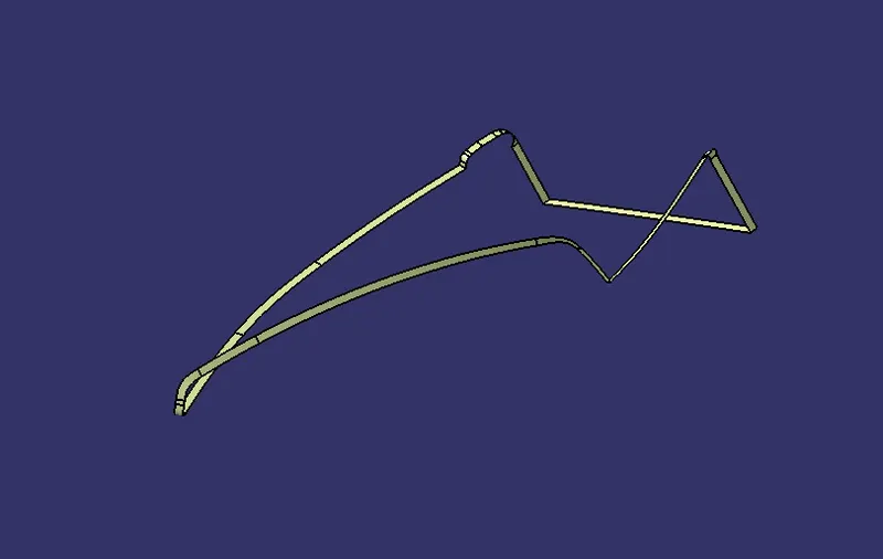
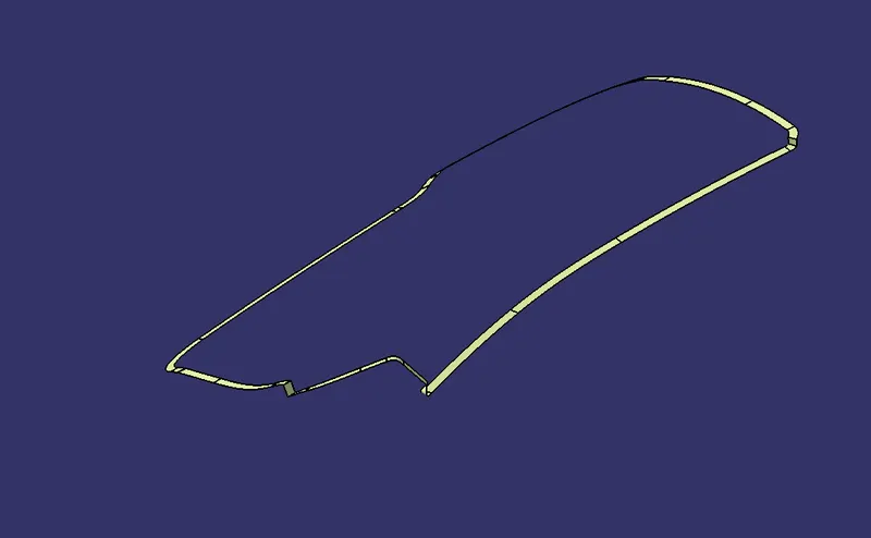
- Class C surface is swept along the boundary of the Class A at an angle perpendicular to the Class A surface with respect to the tooling axis direction with a draft angle of 3 degree.
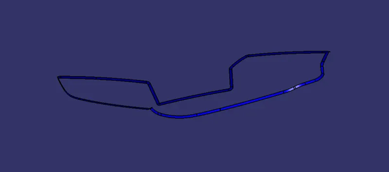
Joining Class, A, B and C surfaces to get a Closed surface:
- After finishing all the 3 surfaces join the Class A and Class C surface together using join command. Now the joined surfaces are then trimmed with the Class B surface to form a Closed surface.
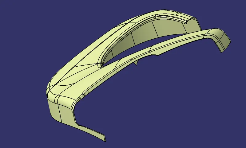
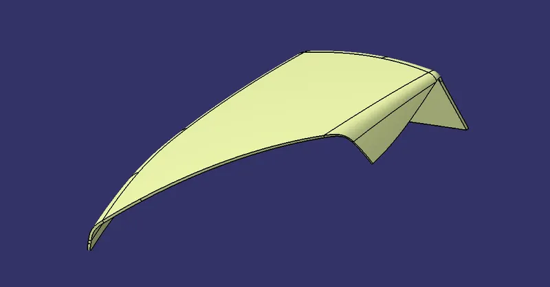
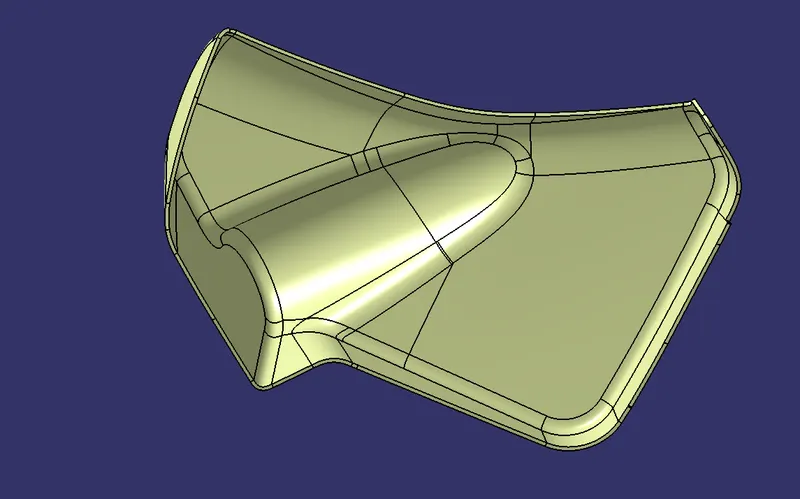
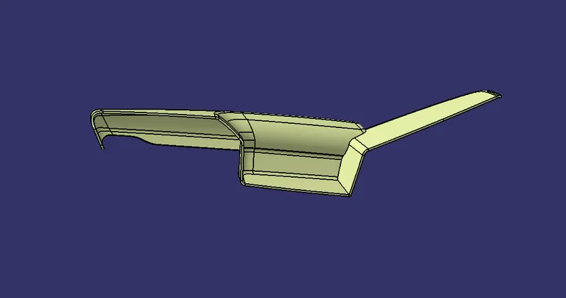
Creation of Flanges, Ribs, Dog house and Heat stakes:
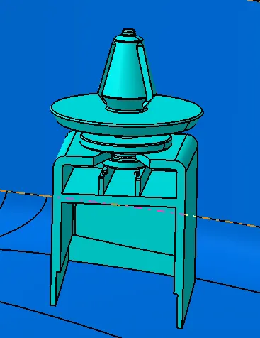
Dog house:
Create the Dog House as per the design rules and give the required draft angle.
- Dog house wall thickness at a intersection of the part wall (C) should be 40% or less than the main wall stock (T).
- Height of (B) should be between 3-6 mm.
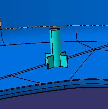
Ribs:
- Create the ribs as the design rules and given the required draft angle.
- Ribs are created to increase the stiffness and strength of the surface.
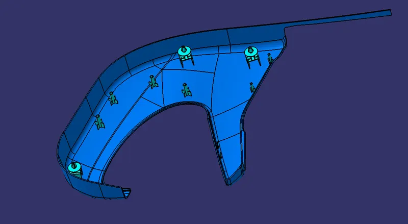
Heat Stakes:
- Heat staking is a pulsed heat process to join two or more parts out of which
- One at least is made of plastic.
- The process to deform the plastic material using heat and force at a set process time. The bond is made bit partially deforming the plastic part in order to fix the other.
Draft Analysis For the Final Components:
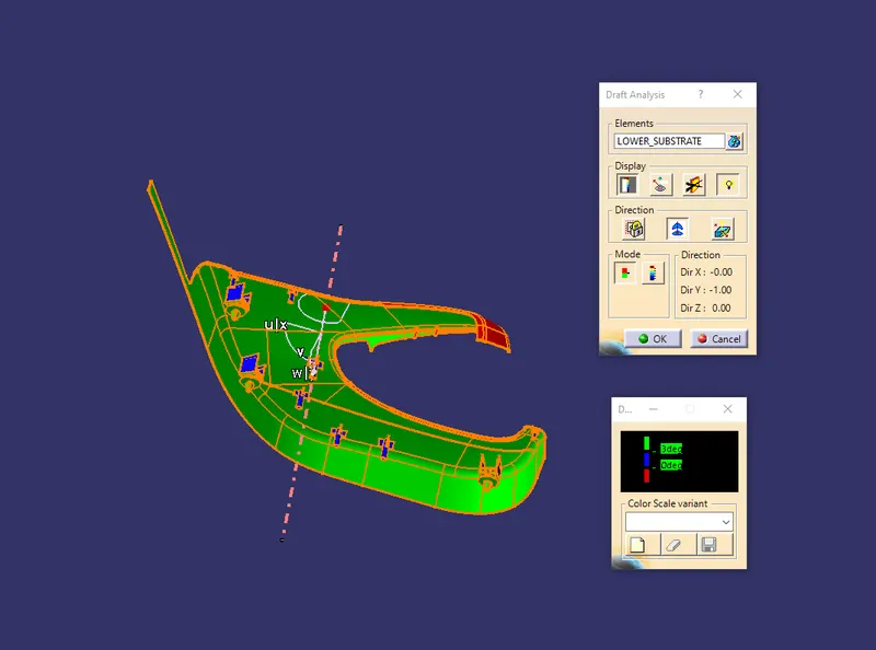
Draft Analysis for the Dog house:
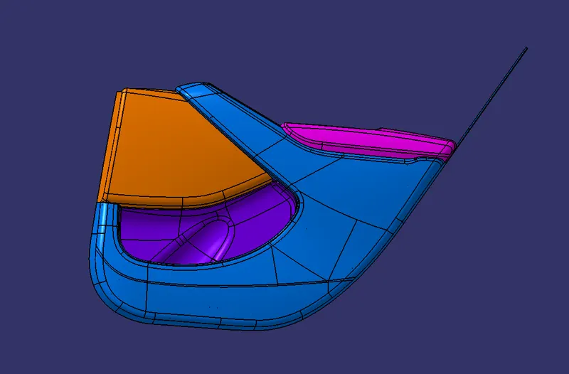
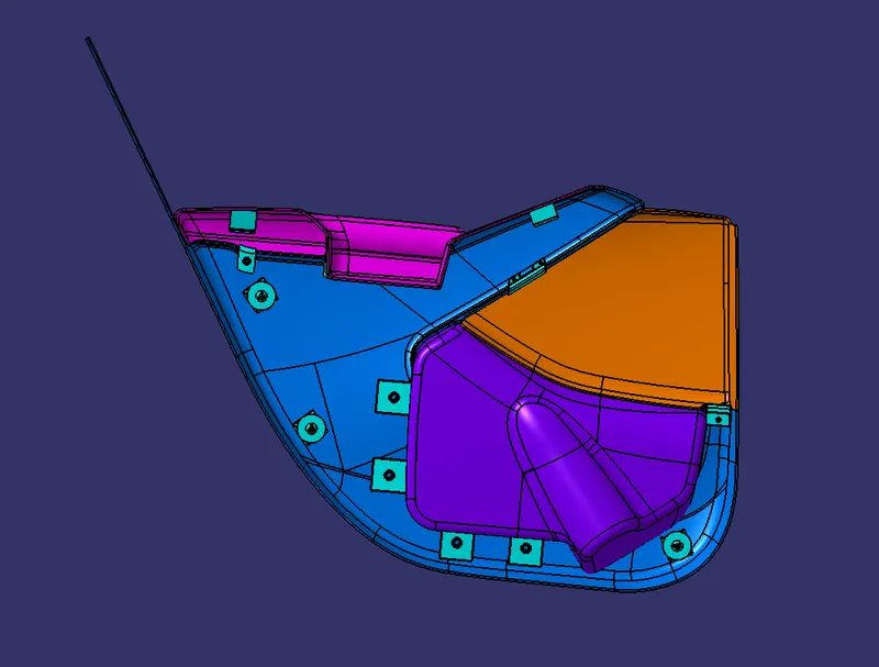
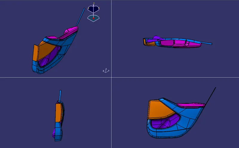
FINAL ASSEMBLY:
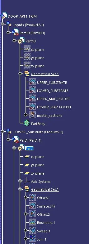
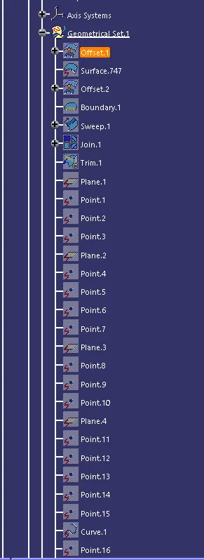
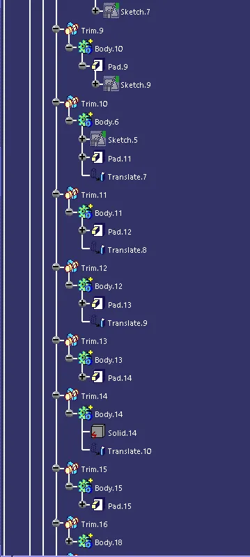
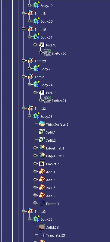
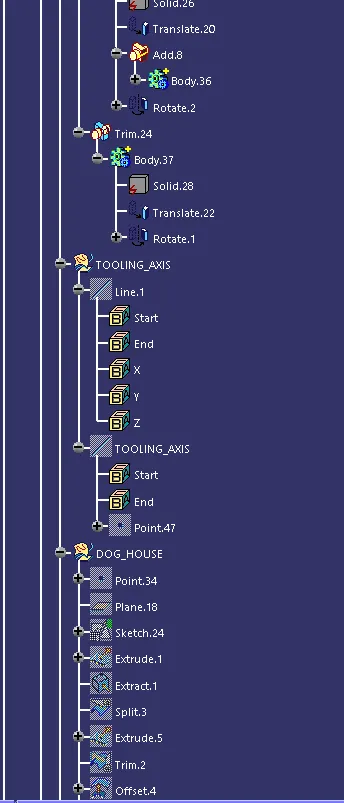
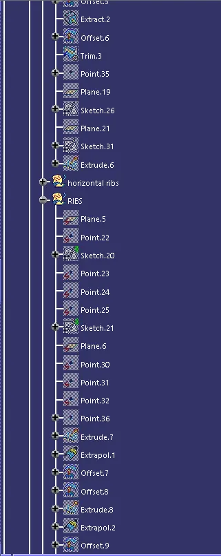
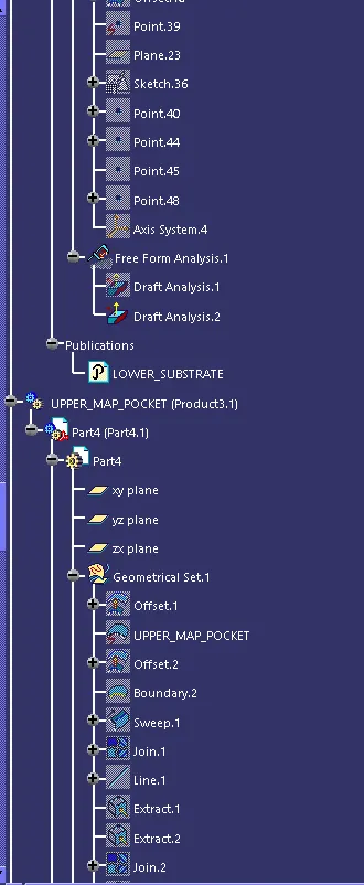
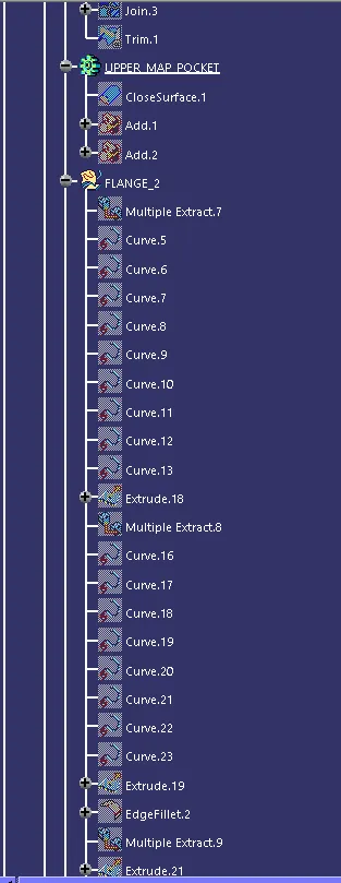
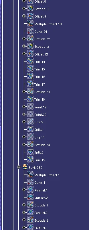
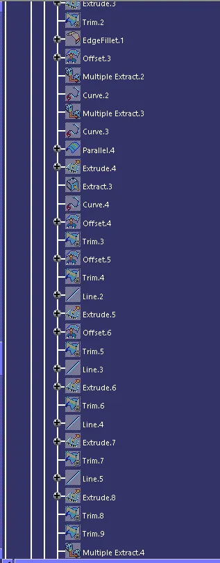
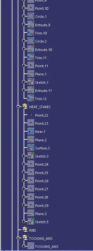
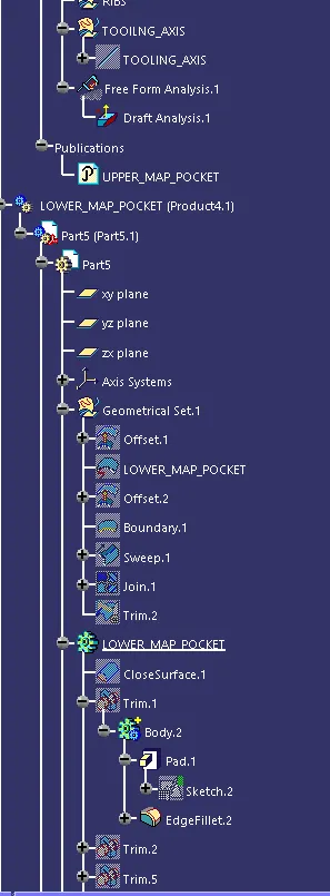
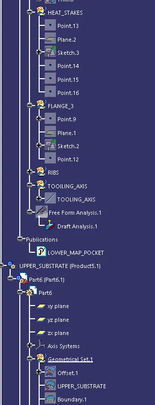
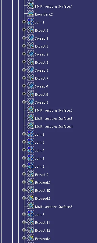
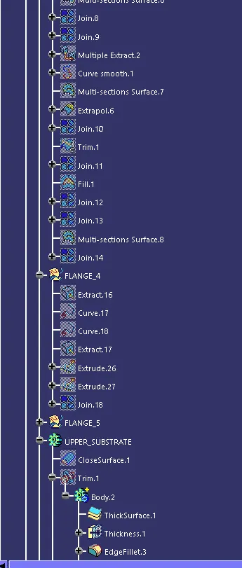
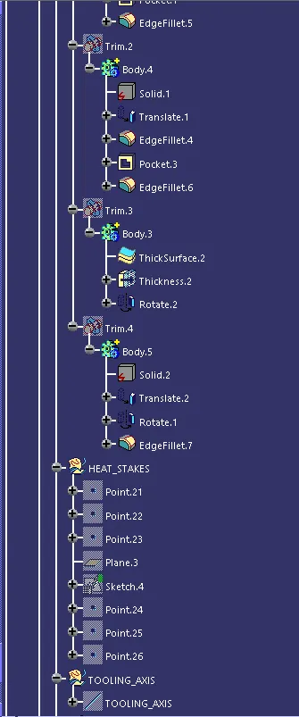
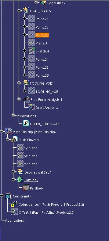
Tree Structure:
 v
v 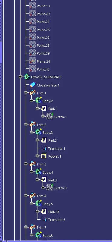
CONCLUSION:
- Class A, B and C surface was created as per the automotive standards using CATIA V5 Software.
- Draft Analysis was performed for the built model and it could be seen the the draft was under permissible limit for the manufacturing of the component.
- B side features were created for the component as per the design rules.