Week 11 - Final project
PROJECT : Plastic design of door trim panel
Content:
- Aim
- Introduction
- Description of project
- Analyzation of Class-A surface
- Creation of tooling axis
- Draft analysis for Class-A surface
- Creation of Class-B surface
- Creation of Class-C surface
- Creation of solid body
- Draft analysis for solid model
- Introduction to attachment features
- Creation of attachment features
- Draft analysis for attachment features
- Assembly
- Views
- Rendering for door trim panel
Aim :
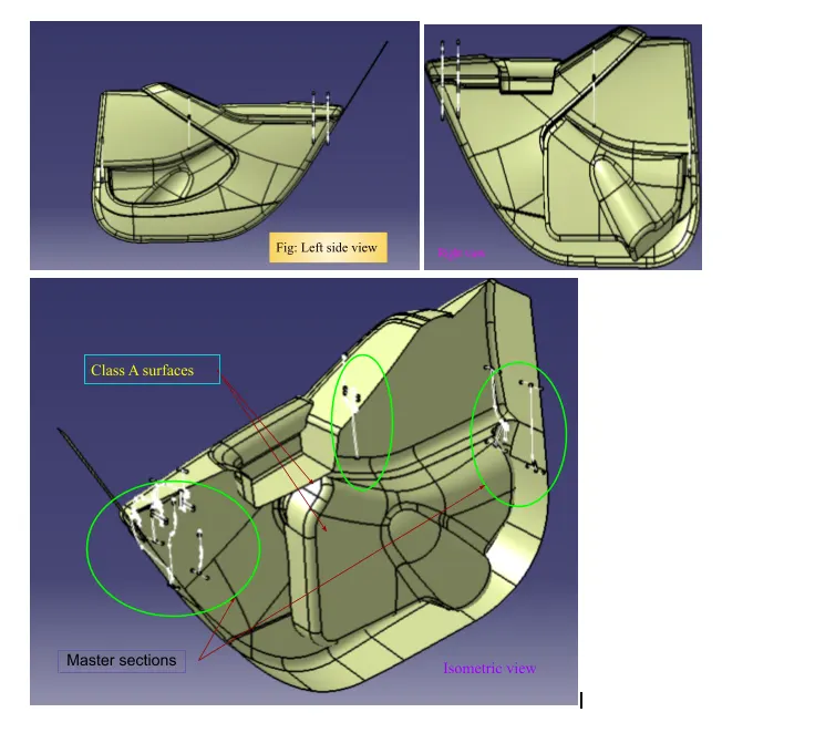
To create a solid body of door trim panel components and attachment features where required , using given input of class-A surfaces and master section , by following OEM standards .
Input file shown below:
Introduction:
PLASTIC DESIGN OF CAR DOOR TRIM PANEL
Polymer:
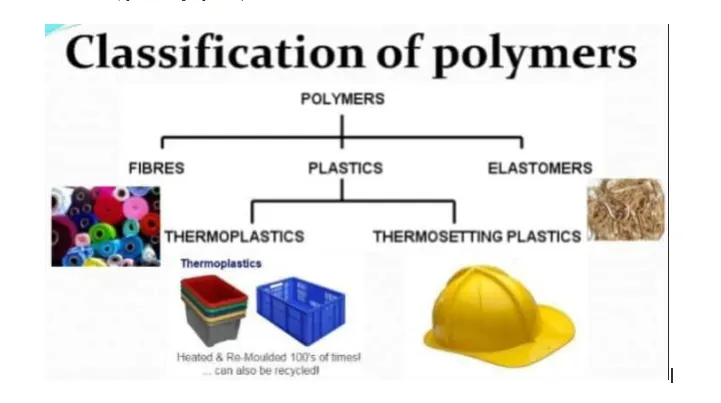
A polymer is a large molecule or a macromolecule which essentially is a combination of many subunits. The term polymer in Greek means ‘many parts’. Polymers can be found all around us.Polymers may be naturally found in plants and animals (natural polymers) or may be man-made (synthetic polymers).
plastic, polymeric material that has the capability of being molded or shaped, usually by the application of heat and pressure. This property of plasticity, often found in combination with other special properties such as low density, low electrical conductivity, transparency, and toughness, allows plastics to be made into a great variety of products. These include tough and lightweight beverage bottles made of polyethylene terephthalate (PET), flexible garden hoses made of polyvinyl chloride (PVC), insulating food containers made of foamed polystyrene, and shatterproof windows made of polymethyl methacrylate.
Plastics are mainly divided into two types: (i)Thermoplastics
(ii)Thermosets
Thermoplastics:
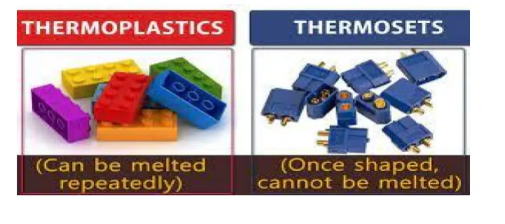
Thermoplastics such as polyethylene and polystyrene are capable of being molded and remolded repeatedly. Thus, a foamed-polystyrene cup can be heated and reshaped into a new form—for instance, a dish.
Examples: acrylic, polyester, polypropylene, polystyrene, nylon,teflon etc…
In today’s world WHY industries are adapting or replacing plastic?
- Plastics reduce the weight of cars
- Plastics and polymers contribute to safety of cars
- Plastics help to lower the manufacturing costa
- Plastics advance the design of vehicles
For example, a modern car weighing 1500 kg, contains about 20% plastics(Thermoplastics and elastomers).
Thermoplastic advantages:
- High recyclable
- Can be remolded and reshaped
- Excellent corrosion resistance
- Aesthetically superior finishes
- Electrical insulation
Thermoplastic Dis-advantages:
- May soften when reheated
- Can be more expensive than thermosets
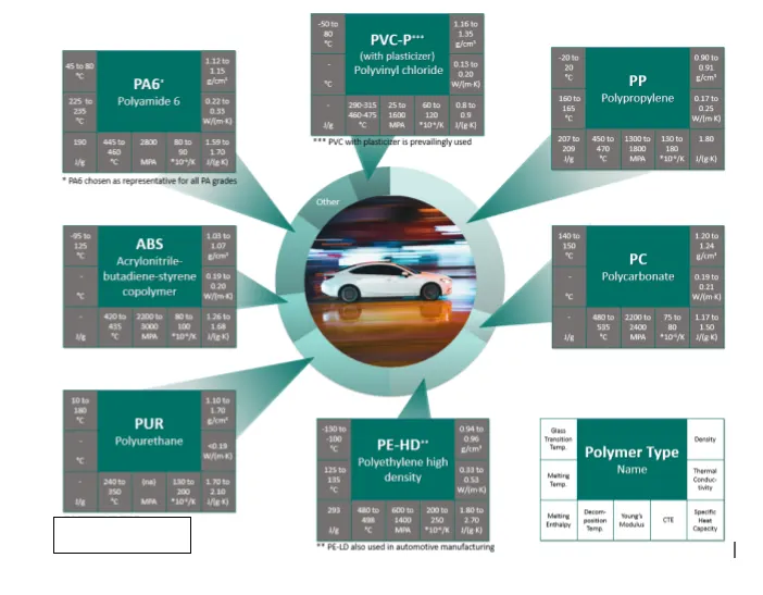
Here are the some most popular thermoplastics used in automotive o through with the below image:
Description of project:
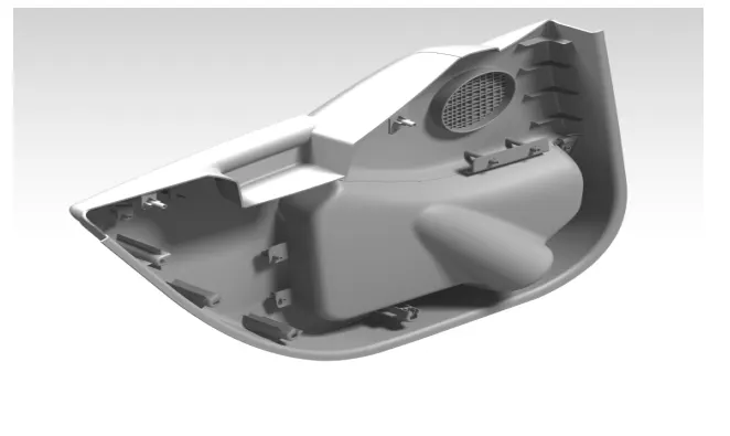
Creating a solid model of door trim panel with reference to given class-A surfaces and master sections for respective components. Door trim panel is a combination of applique,switch bezel,arm rest, speaker grill,lower map pocket,upper map pocket, lower substrate, upper substrate and grab handle.
As per data given, I worked on upper and lower map pocket, lower substrate, arm rest and attachment features.
Follow the below pictures for Class-A model and actual part :
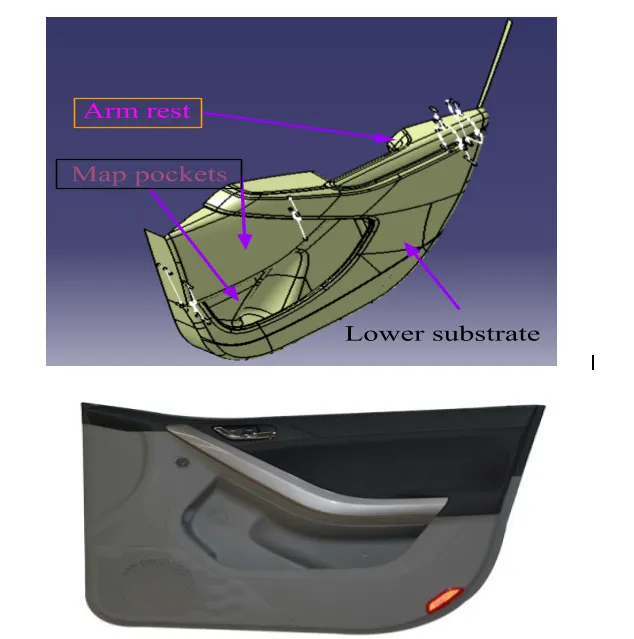
To create a solid model we refer to the class-A surface model , which is created in autodesk alias software by engineers and for the body thickness and to locate the attachment features we follow the master section to create it.
Analyzation of CLASS-A surface :
To create a solid model we get class-A surface for a particular model, before working on it we need to analyze the CAD data like what? By means, checking its basic things like checking connectivity or boundaries. Why do we do that? Because if there is a gap in there , then I need to inform the class-A engineers who created it to do correction.Always we don't get the proper class-A surface .
Follow the below images to know about boundary and connectivity :
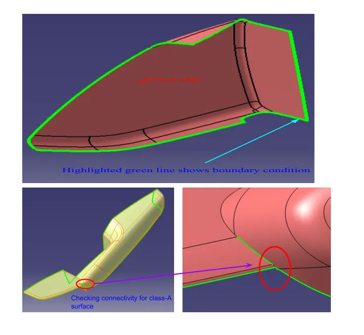
As shown in above picture, there is a gap in class-A surface so need to be informed to recorrect it and standard merging distance value for class-B surface is 0.001mm to 0.003mm.Class-A merging value varies from 0.1mm to 0.3mm.
Creation of tooling axis:
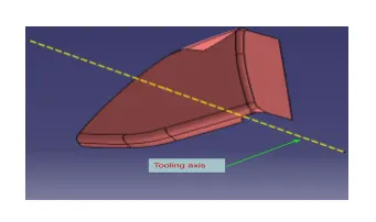
What is the tooling axis?
Tooling axis is the axis which gives direction to move the core and cavity and ejection of parts without damage. Molten metal flows in it through a nozzle.
Methods to creating tooling axis:
(i)Bisecting method
(ii)Compass method
(iii)Sketching method
Compass method:
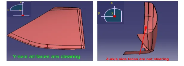
First we need to check in which axis all faces of the part are clearing, in that direction we create a dummy tooling axis to create the main tooling axis for the part .
Follow below pictures for reference:
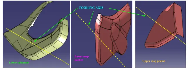
Same method is used to create tooling axes for lower and upper map pocket, lower substrate . follow below picture:
For arm rest tooling axis follow below picture of compass method:
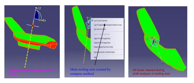
Applications:
(i)It is used for draft analysis for respective parts.
(ii)It is used as direction to create class-C surface.
Draft analysis for class-A surface:
This method enables us to detect if the part we drafted will be easily removed during manufacturing and it meets the standard values of draft angle for the molding process. This analysis is performed based on color ranges with different colors and draft direction at any point.
Draft analysis is done with respect to the tooling axis and it should meet its standard draft value.
Minimum draft value for plastic parts is 3degree.
Draft analysis is done with respective parts follow below pictures:
(i) Lower substrate and upper map pocket:
All faces are meeting draft value
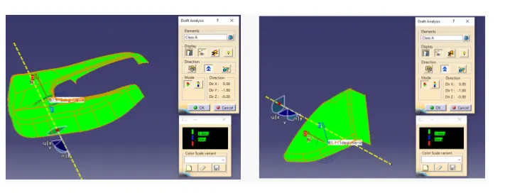
(ii)Armrest draft analysis through main tooling axis:
All faces are meeting draft value
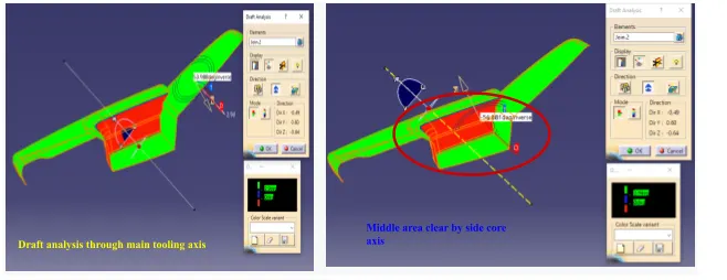
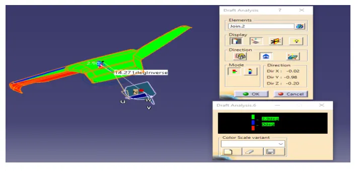
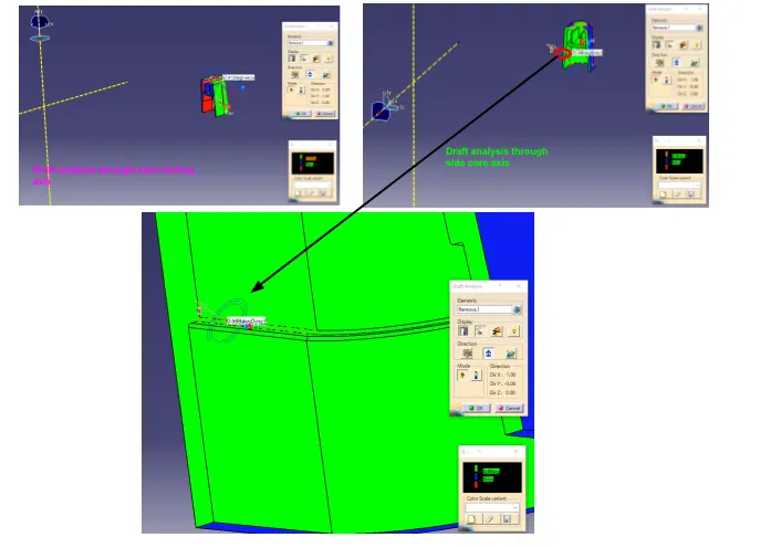
Armrest draft analysis through side core axis :
Meeting draft value
(iii)Lower map pocket draft analysis:
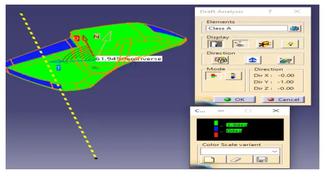
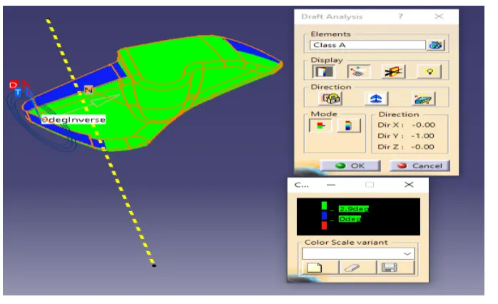
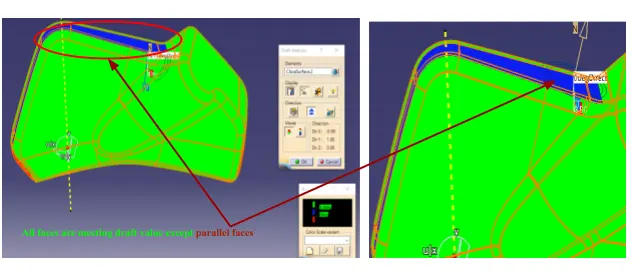
Due to parallel faces during draft analysis we get 0(zero) degree draft angle at those areas, this type of issues need to be addressed to class-A engineers and need to be told to create part with providing angle at sides.
Follow the below image:
Creation of class-B surface:
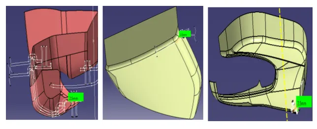
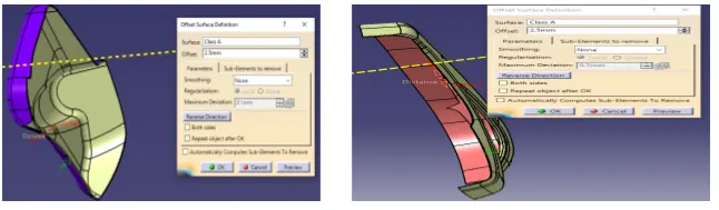
In plastic design class-B surface created by off-set and trimming method. The off-set value we get from the master section and thickness of plastic product minimum is 2.5mm.
For complex parts we use off-set method to create class-B because it has so many patches to extract and to work for trimming operations. It is also a time saving operation.
To create class-Bsurface ,we get the value from master section as shown in the below images:
By off-set method created class-B surface follow below images:
Class-A is always on the visible side and class-B is always on the opposite side of it .
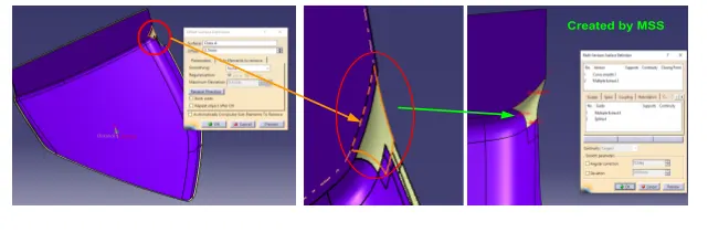
While off-setting class-A surface, sometimes for the fillet portion we cannot offset,that time we use a multi section surface, different types of sweep method to create it and join with the offset part to complete the part.
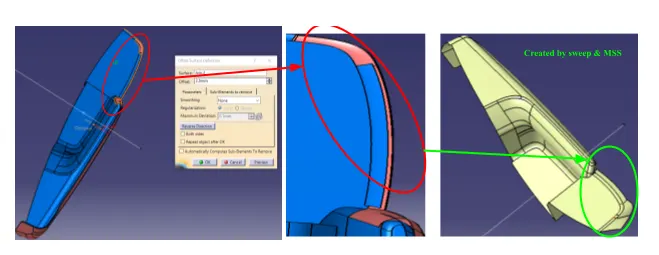
For upper map-pocket and arm rest i used same methods to create those areas, as shown in below:
Creation of class-C surface:
Generally class-c surface is the connection between class-A and B surfaces angled direction with main tooling axis and side core axis if it is there.
I created class-C surface
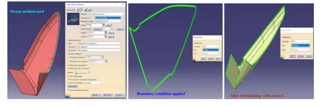
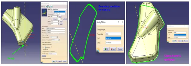
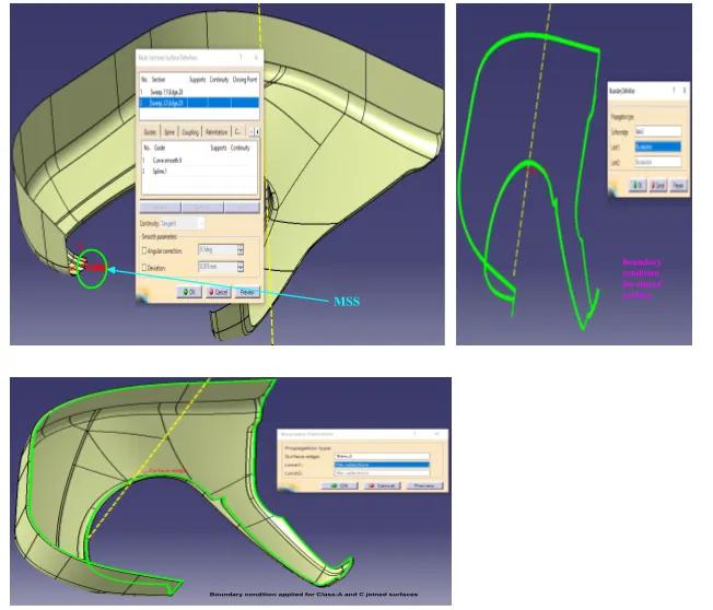
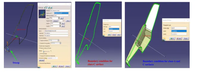
(i) using sweep and multi-section surface tools by using class-A boundary as guide curve and spline (where required created).
(ii)After completion of creating class-C surface , do joining operation for class-C surface. Then do trimming or joining operations with class-A surface to create on a single surface.
(iii)At last check the boundary condition to check if there is any gap.
same procedure applies for all respective parts to create class-C surface.
As shown in below images class-C surface creation:
Upper map-pocket:
Lower map-pocket:
Lower Substrate:
Armrest :
Creation of solid body:
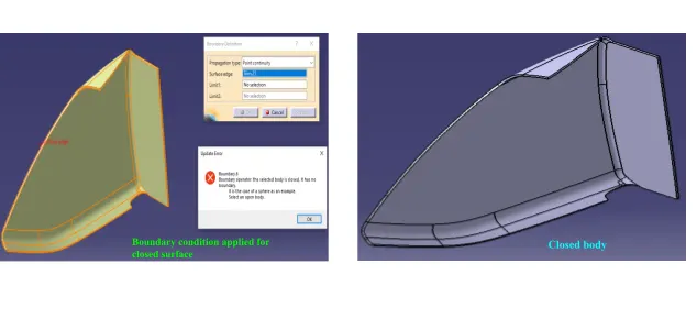
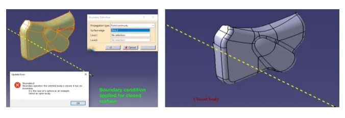
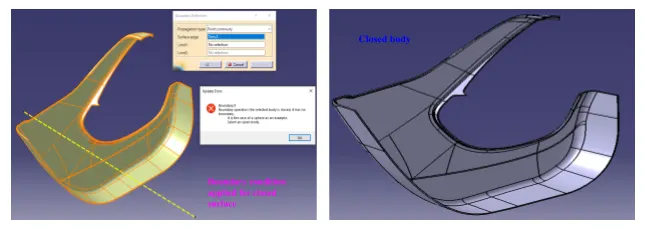
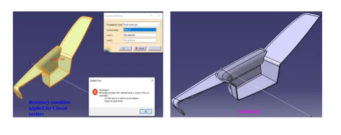
After creation of class-C surface joining or trimming operation with class-A surface to create a single part.Then trim class-C and A surface with class-B to get the final part / closed surface for that we need to create a solid body in part modeling.
For the final part apply the boundary condition if you still get a boundary, it means it has a gap if it is not then it is a closed body.
Same process follows to respective parts, as shown in below pictures:
Upper map-pocket:
Lower map-pocket:
Lower substrate:
Arm rest:
Draft analysis for solid body:
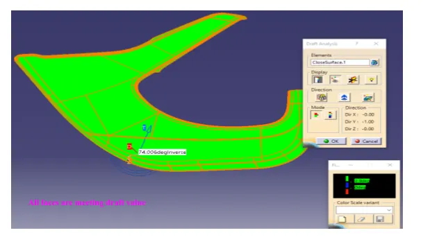
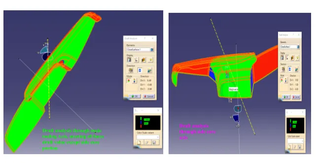
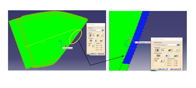
As we did draft analysis for class-A surfaces for respective parts to check if they meet draft value , same thing we check for solid bodies.
Follow the below images of draft analysis for respective parts:
Lower map-pocket:
For parallel face got draft value 0 (zero) degree
Lower substrate:
Arm rest:
Upper map-pocket:
Introduction to attachment features:
Attachment features are also called engineering features or B-side features , which are mainly used in assembly or joining similar or non-similar parts .
Some of them are:
(i)Ribs
(ii)Screw bose
(iii)Dog house
(iv)Heat stakes
(v)Locators and many more .
We know ,while designing plastic parts or products we must follow design rules as per the respective parts. So while designing attachment features we have to consider DFM(design for manufacturing) and DFA(design for assembly) guidelines.
Creation of attachment features:
While creating attachment features, first we need to know where to locate those. We get the information of location and some dimensions in the master section which we received along with scanned data of Class-A surfaces.
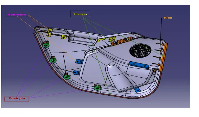
Dog house:
Dog house is an engineering feature used in plastic trim design. Dog houses are used as supporting features. Sometimes other engineering features like snaps, locators etc. are mounted on them to increase their strength. Dog houses are subjected to draft analysis to prevent breakage of the component during ejection from mould cavity. Dog house and other engineering components are built on a B-surface.
Design guidelines for creating dog house follow as below:
(i)Wall thickness must be maintained uniformly.
(ii)Corner radius.
(iii)Draft angle.
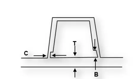
In above figure where,
- Height of “B” should be 3mm to 6mm.
- Width (w) : Minimum 12mm
- “C” is where the doghouse contacts the backside of the surface.
- Draft angle at outside surface minimum 2.8 degree.
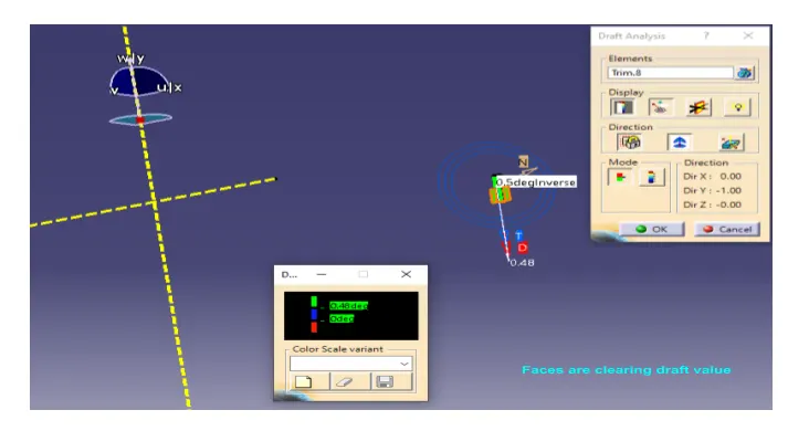
- Draft angle for inside faces minimum 0.48 degree.
- Fillet at the inner side:0.25* thickness(t)
- Fillet at the outer side: 1.25* thickness(t).
Draft analysis for dog house :
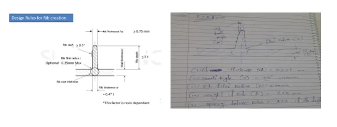
Ribs:
Ribs are a feature in plastic injection molded parts. They are thin extensions that run perpendicular from a wall or plane. They are commonly used to provide additional support and strength to a part.
Heat stakes:
Heat staking also known as thermoplastic staking is the process of joining two dissimilar materials together. In heat staking we use local heating and cooling to raise the temperature of plastic components and allow plastic reforming to be carried out. This reforming can be used in a wide variety of applications.
Applications range from staking plastic boss’s for assembly of car door panels to joining PCB’s to plastic housings. Benefits of this technique include; no vibration damage, no particulates, the ability to stake metalized coated applications and the capability to stake in difficult to access or restricted areas.
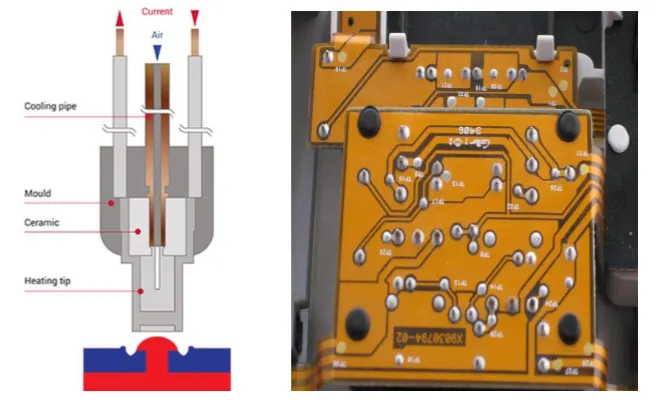
Applications:
- Polymer to Polymer to other materials
- Flat head tip welding
- Sealing holes
- Embedding parts
- Polymer to mesh
- Breathable membrane
- Rim Swaging
- Bonding
- Polymer to polymer welding
- Polymer to polymer
Draft analysis for heat stakes:
Assembly :
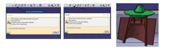
After creating a solid body and attachment feature , the last step is to do assembly. First assemble push pin with respective dog house.
Procedure:
(i) Axis constraints of push pin and dog house, then give the update.
(ii)Surface contarints for lie on respective position on dog house .
Same procedure applies for door trim panel assembly
Follow the below pictures:
Views:
(i)Final body :
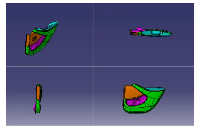
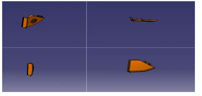
(ii)Upper map pocket:
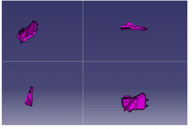
(iii)Lower map pocket:
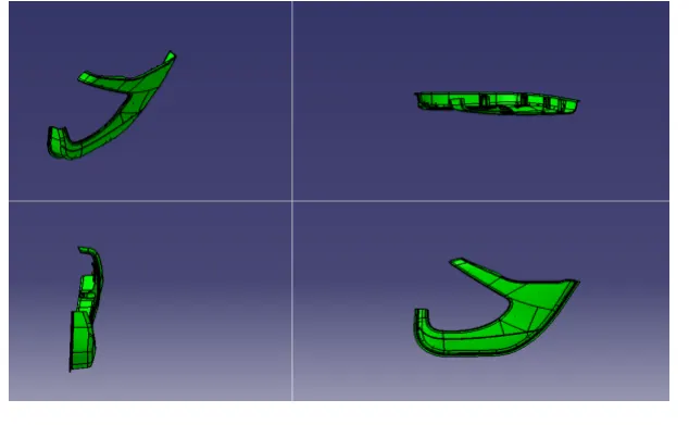
(iv)Lower substrate:
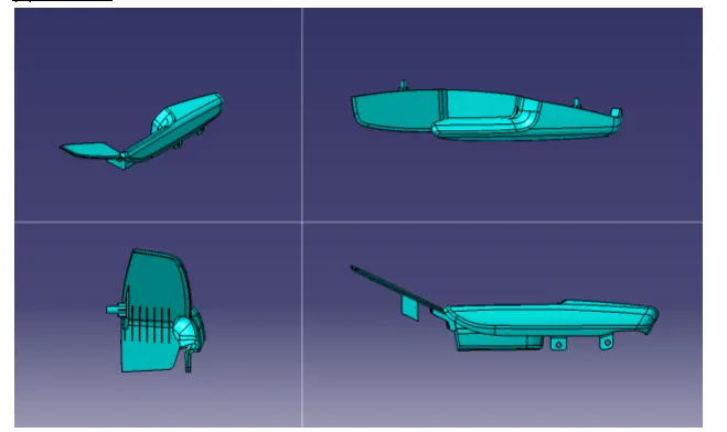
(v)Arm rest:
Rendering: