Week 11 - Final project
Development of a Door Trim panel
Software: Catia V5
Right Handside Door Trim Panel
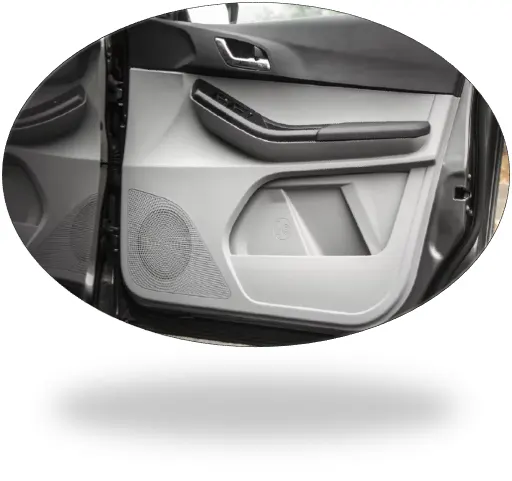
Car door panel Back Side
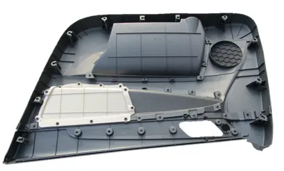
Aim and Objective:
- Create a CAD model considering Class A surface as an input,
- Refer master sections for Nominal thickness,
- Create the mounting features as per design guidelines in the industry and with master sections,
- Perform Draft analysis using desired Tooling analysis.
Introduction:
- Design flexibility, Corrosion resistance, Overall aesthetics, and desirable mechanical properties make polymers a favorable choice for interiors.
- Plastics represent only about 10% of the weight of today's vehicle but about 50% of the volume.
- Plastics help reduce noise, vibration, and harshness in the vehicle interior.
- The door inner panel is made up of Plastics and is one of the most important interior components.
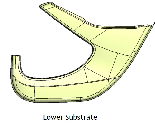
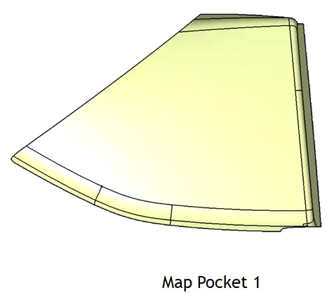
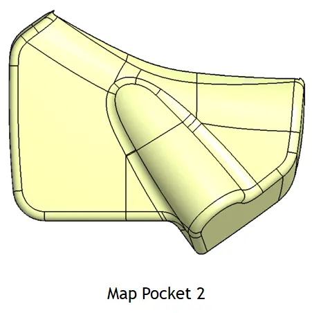
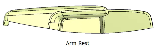
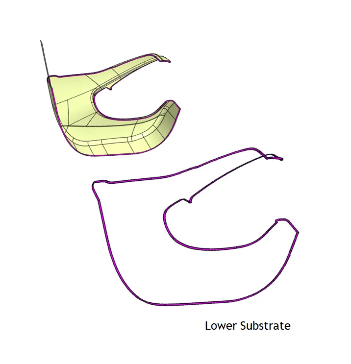
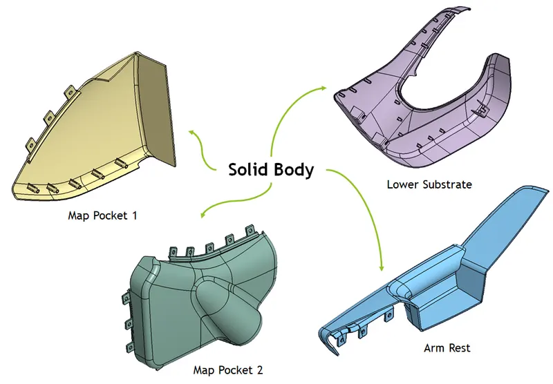
- Generally, Door trim parts are divided into different parts for ease of manufacturing, i.e. Lower Substrate, Map pocket, and Armrest
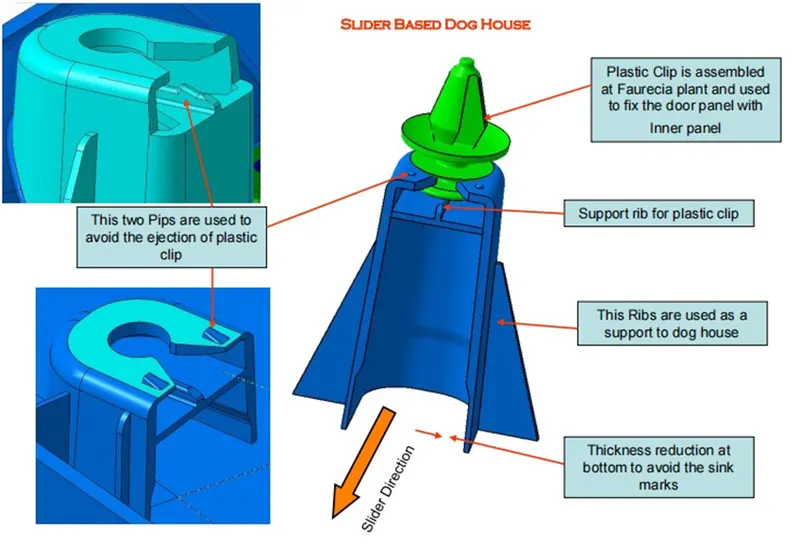
- Development of Door Trim Panel with attachment features such as, Ribs, Heat Stakes, Dog House, Push Pins, Flanges, has been discussed in this report.
- Draft analysis is performed to check is tooling feasibility.
Input Class A Surface
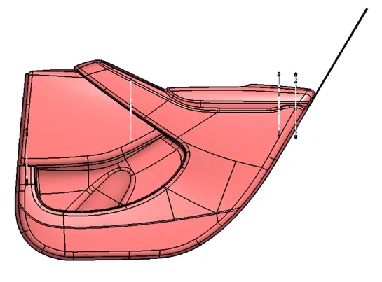
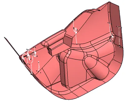
- Class-A (or 'Strak') is a term used specifically in automotive design. It is either as a scanned clay model or an CAD model.
Input Master Section
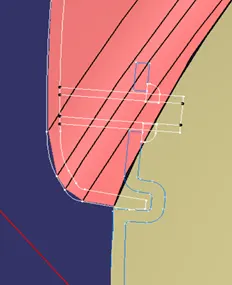
- Mater sections are used to identify Profile, Parts thickness and Engineering features.
Extracted Class A Surface
- Input Class A surface is analysed and extracted to create final Class A Surface.
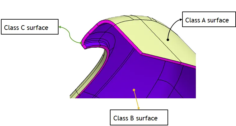
- Class A surface is aesthetically important and also contains styling and texture.
- It does not have any attachment and engineering features like Ribs, Dog house, Heat stakes, Screw boss, etc.
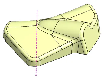
Tooling Axis Creation
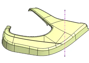
- The direction in which the core and cavity of a mold opens is called as tooling axis.
- In this case, tooling gets cleared along the Y-axis, hence any point on the surface is taken as reference, and the line is drawn along Y-axis.
- This line is considered as the tooling axis of that particular part as shown in the figure below,
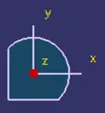
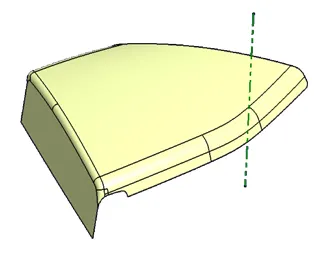
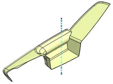
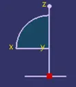
- In case of Armrest, tooling gets cleared along the Z-axis, hence any point on the surface is taken as reference, and the line is drawn along Z-axis.
- This line is considered as the tooling axis of Armrest as shown in the figure below,
Draft analysis
The draft is an angle provided to the part with respect to the tooling axis to reduce friction between Part and Mould.
Lower Substare Draft analysis
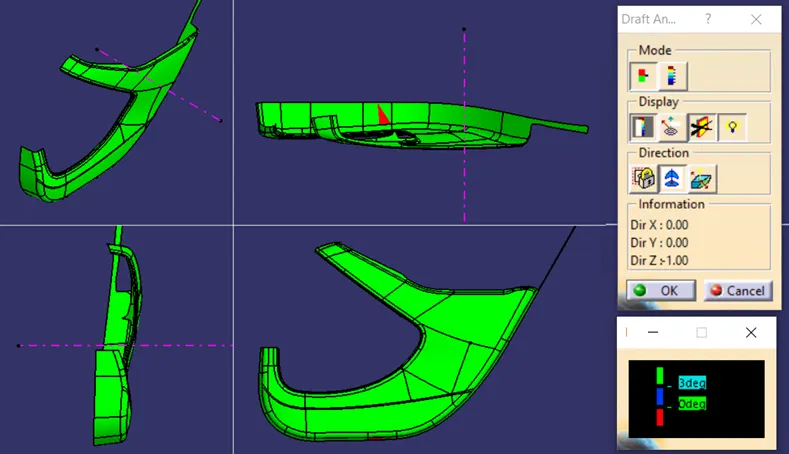
- Lower Substrate has minimum 3 degrees of draft.
- Area highlighted in red does not meet draft requirement for tooling, hence needs modification.
Map Pocket 1 Draft analysis
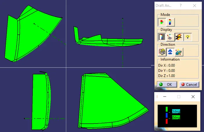
- Map pocket 1 has minimum 3 degrees of draft.
Map Pocket 2 Draft analysis
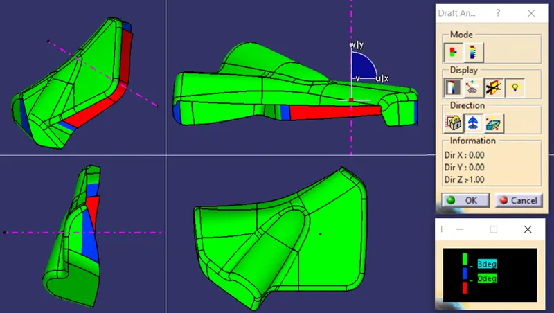
- Map pocket 2 has minimum 3 degrees of draft.
- Area highlighted in red does not meet draft requirement for tooling, hence needs modification.
Armrest Draft analysis
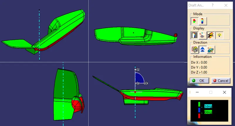
- Arm Rest has minimum 3 degrees of draft.
- Area highlighted in red does not meet draft requirement for tooling, hence needs modification.
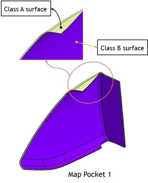
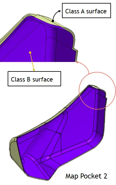
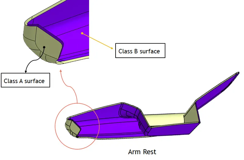
Class B Surface Creation
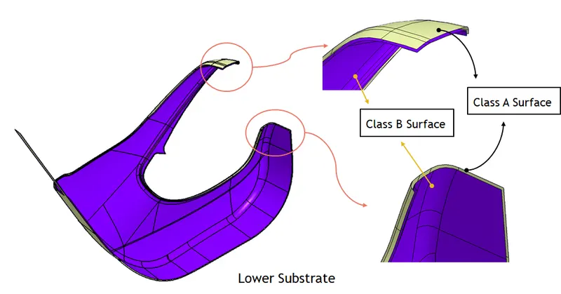
- Class B surface is back side of Class A Surface, all attachment and engineering features are present on this surface.
- It is basically offset from Class A surface to a desired thickness of which part is to be made.
- Class B surface, does not contain any styling and texture.
- It is aesthetically less important and not visible when part is assembled.
Class C Surface Creation
- Class C surface connects Class A surface to Class B Surface.
- Class C surface is swept with draft along tooling direction.
- While designing mould, Core and Cavity are designed in such a way that Parting line is present on the intersection of Class B and Class C Surface, so that while molding any Flash generated will be present on B side of the product.
- It is done purposefully so that, while removing flash any tooling mark will not be visible on Class A surface.
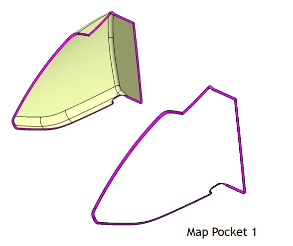
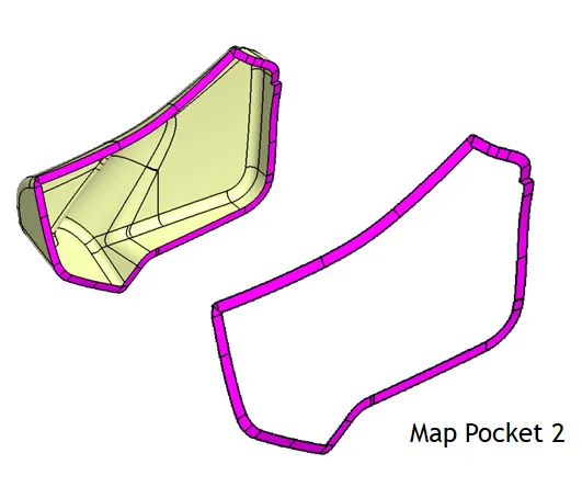
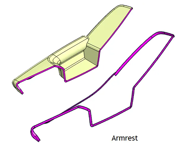
Final Trim & Solid Body
- Finally, Class A Surface, Class B Surface, and Class C surface are trimmed together to form a cavity of desired thickness.
- By using the Close Surface command Solid body is formed of the required shape.
B Side Engineering Features
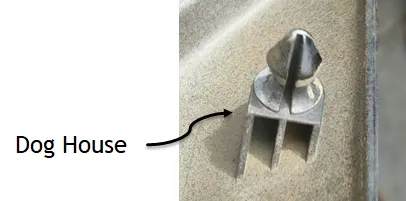
- Dog house is used to increase height of any other feature such as Ribs, Heat stakes, Push Pins, Screw boss, etc.
- Also it acts as supporting feature used for assembly fixation.
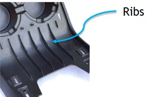
- Ribs help in strengthening the molded part without adding to wall thickness.
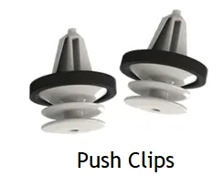
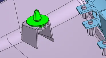
- Push clips used to clamp two parts together, and are used in multiple points for rigid assembly.
 |
|  |
| 
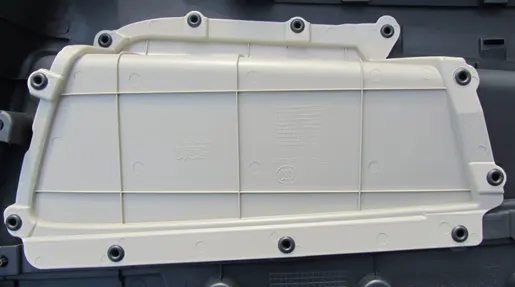
- Heat Staking:
- The process involves heating and compressing a plastic peg so as to soften and deform it in a controlled manner after it has been inserted through a hole. Hot air is commonly used to heat the boss above the glass transition temperature.
- A staking punch is then used to compress the peg, squishing it into a new shape, mechanically locking the two (or more) pieces together.
Engineering Features Draft Analysis
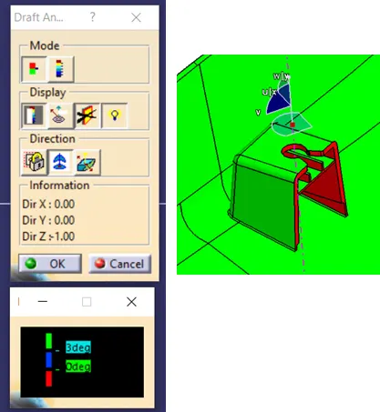
- Dog house has minimum 3 degrees of draft along Y-axis
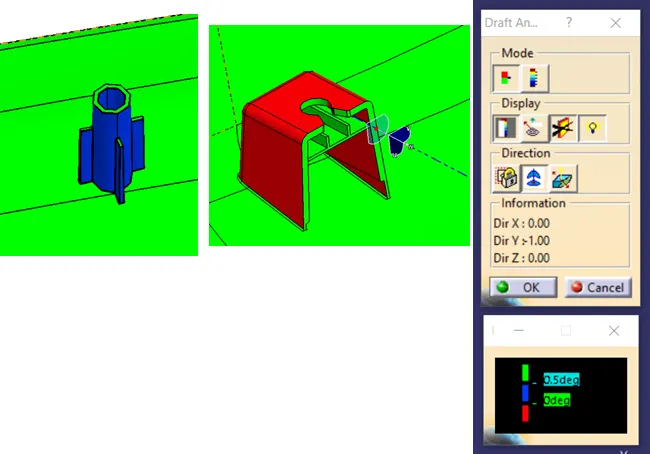
- Heat Stake along with ribs are tooled along Y-aixs and has 0.5 degrees of draft.
- Dog House has minimum 0.5 degrees of draft along lifter axis, areas highlighted in red needs modification.
Final Assembled Door Trim Panel
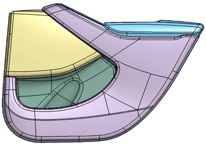
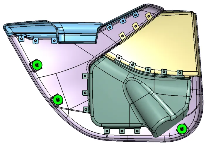
- Finally all solid bodies are fixed together to form a complete Door trim assembly.
Thank you!!!
Please Click/ Browse on the link mentioned below for a Presentation on the Development of a Door Trim panel.
https://drive.google.com/drive/folders/1ZVy7dj6awSLrm06Hm7boCa416VU4LVYD?usp=sharing