Week 11 - Final project
DOOR TRIM PANEL :-
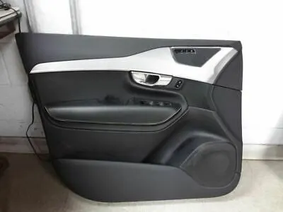
Door panels serve as an interface between the interior of the car and the inner workings of the door, and between vehicle occupants and the door.
CLASS A INPUT SURFACES :-
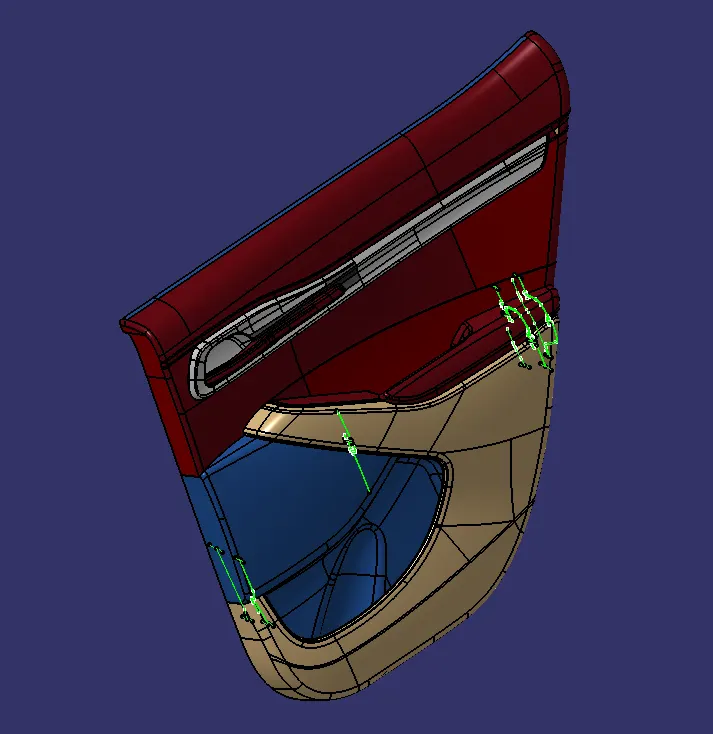
The given below model is the input surface model of the door trim panel. By using this references created door trim panel part bodies.
PART IMAGES :-
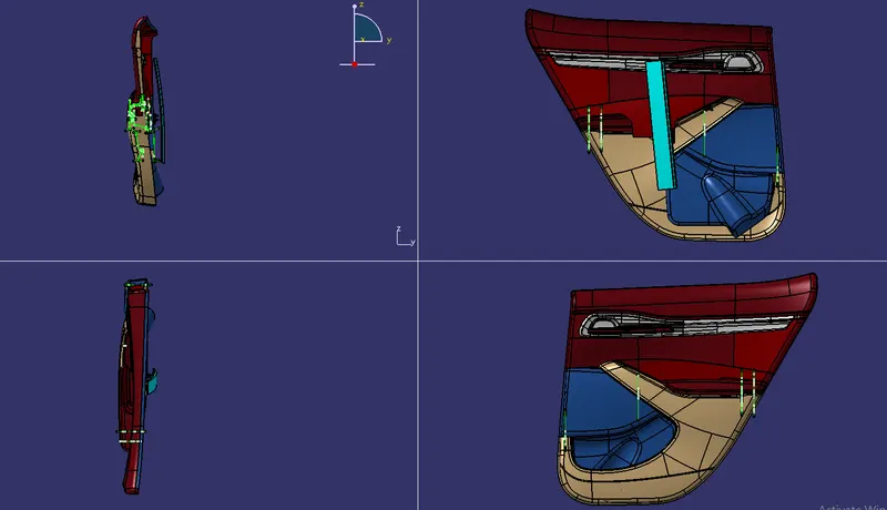
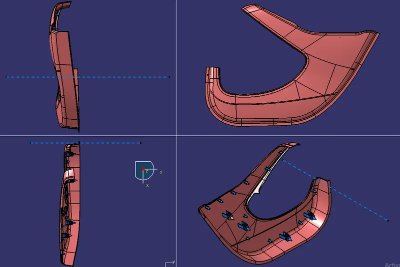
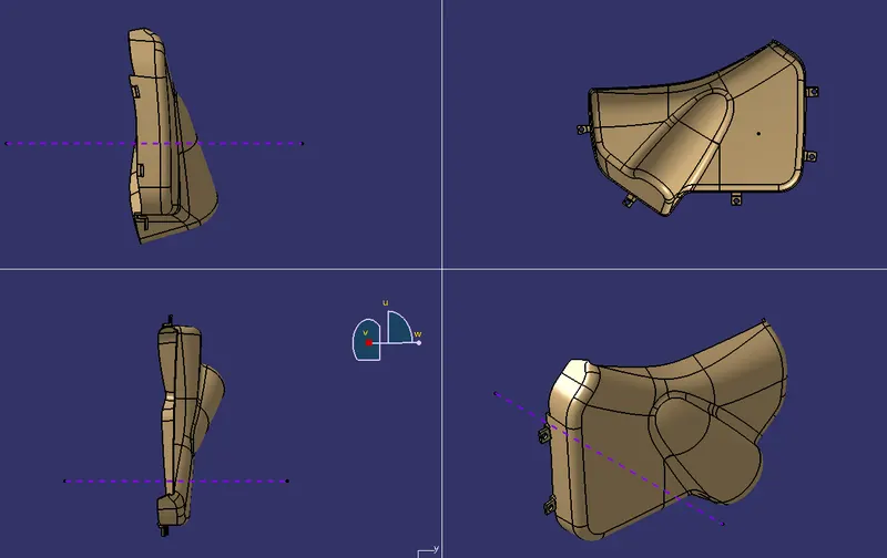
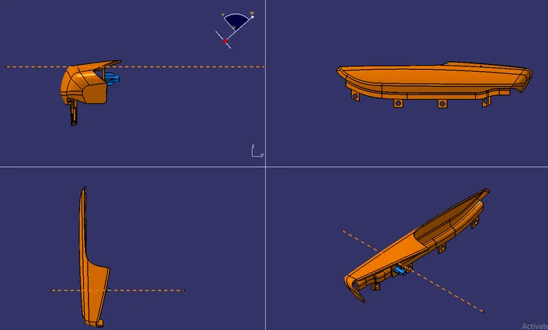
In the given below diagrams represented the part images i.e, Front view , side view , Top view and Isometric view.
PROCEDURE :-
1. LOWER SUBSTITURE :-
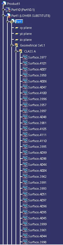
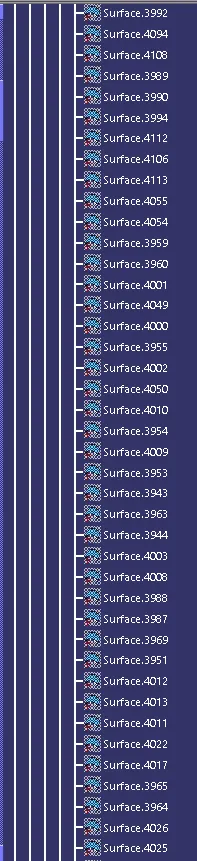
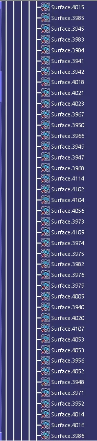
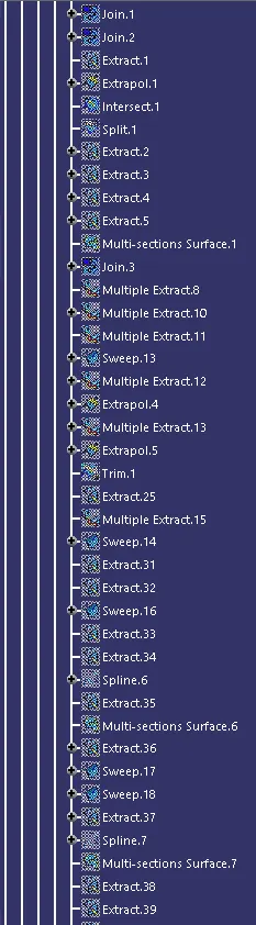
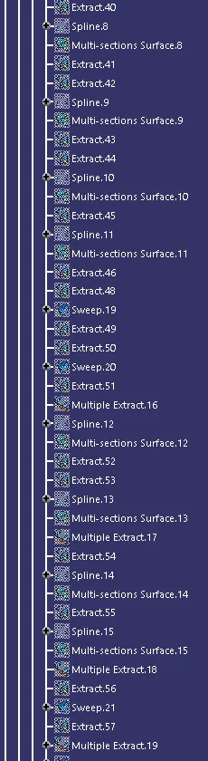
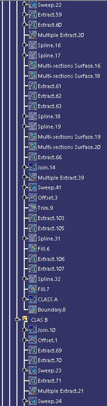
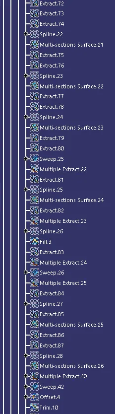
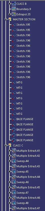
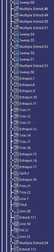
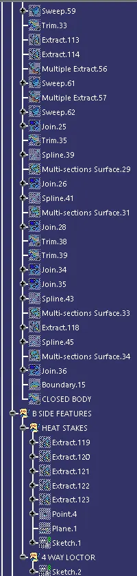
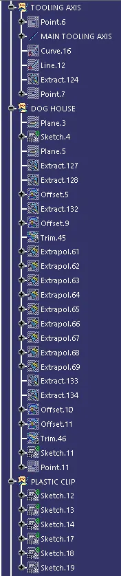
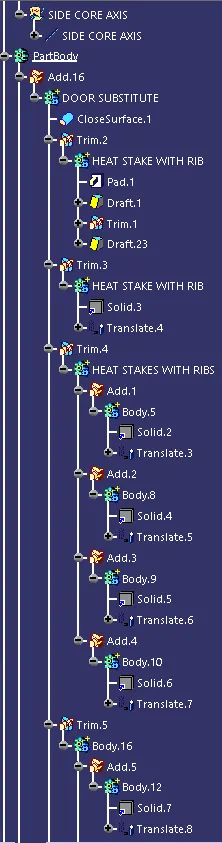
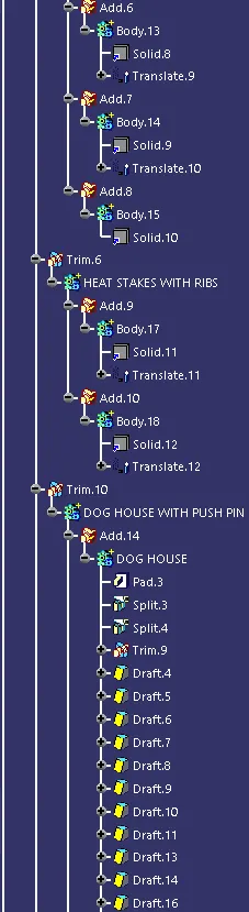
FEATURE TREE :-
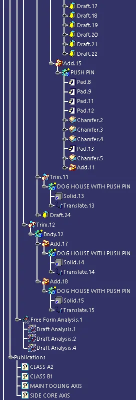
JOINED CLASS A :-
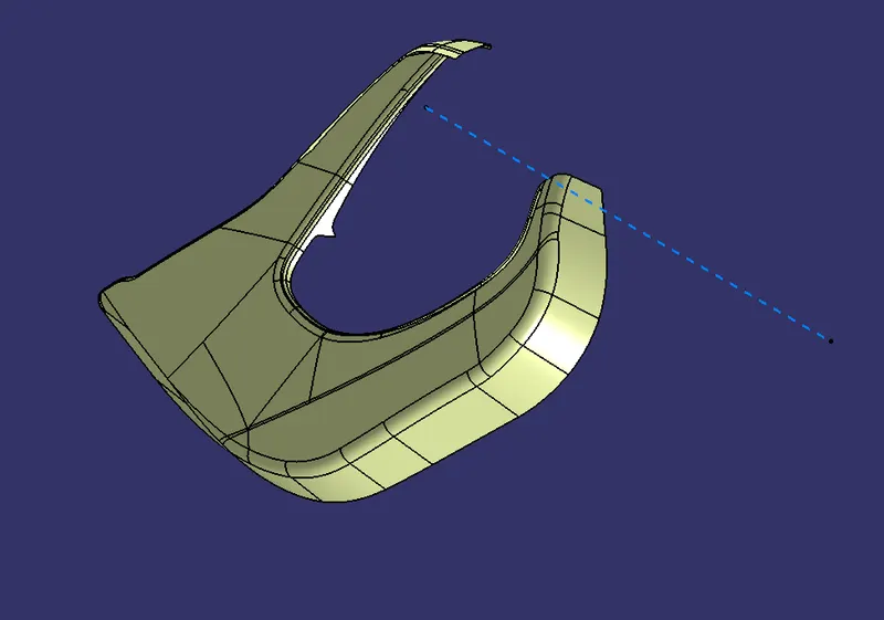
This class A is obtained by the joining of lower substitute surfaces from the input surfaces. And then tooling aixs is created with normal to the surface.
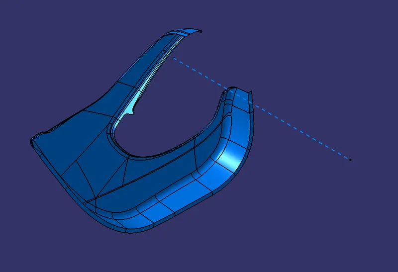
FINAL CLASS A WITH FLANGES :-
In this the flanges are created by using the references from the master sections and the swept coomands.
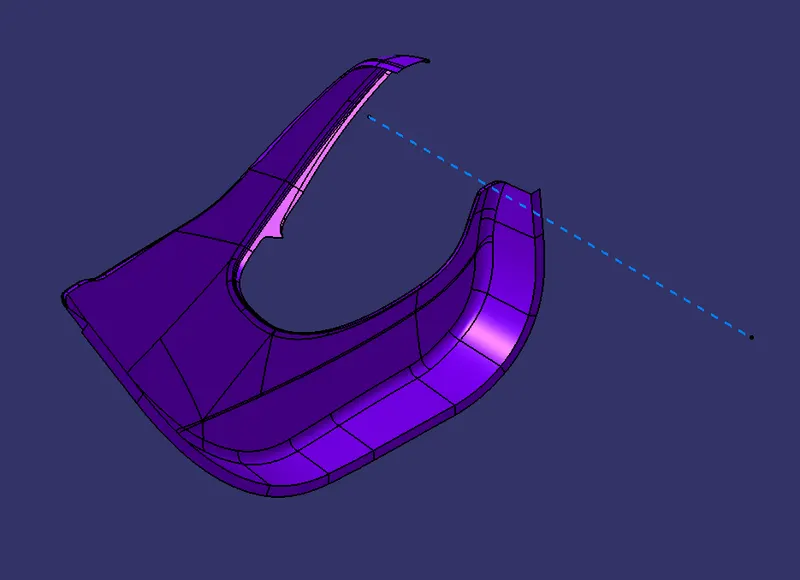
CLASS B SURFACE :-
The below class B surface is created by the offsetting the class A surface for 2.5mm . The offset distance is obtained by the master section references.
CLASS C :-
The class C surrface is created by the swept coomand . The swept is created from the boundary of class A surface.
CLOSED BODY OF SUBSTITUTE :-
Finally by trimming the class A , class B and class C together we get a Closed body of lower substitute.
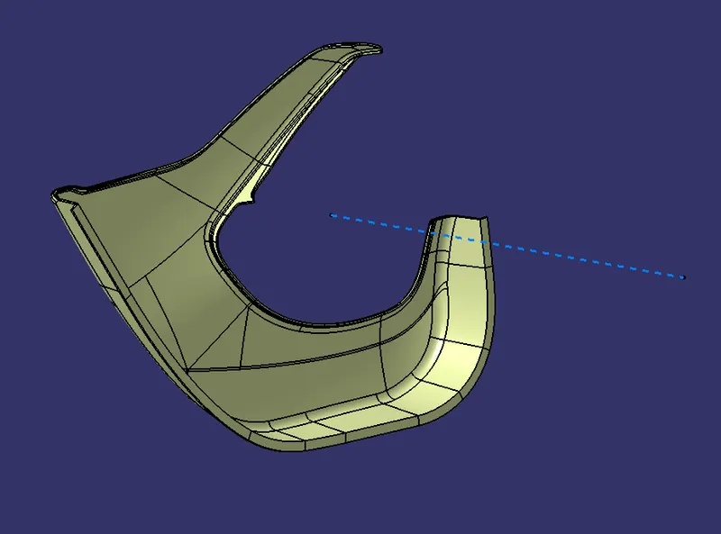
PART BODY OF SUBSTITUTE :-
BY using close surface coomand the closed surface body get converted into part body.
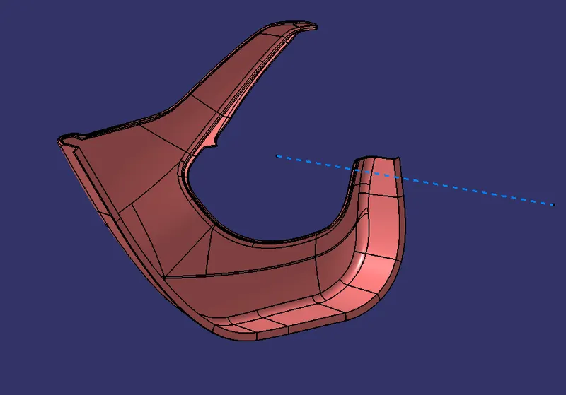
ATTACHMENT FEATURES FOR SUBSTITUTE :
a.HEAT STAKES AND RIBS :-
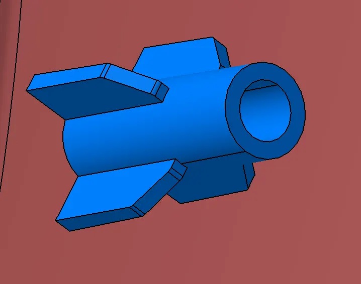
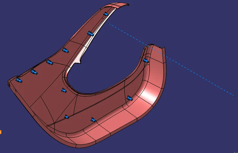
Heat stakes and ribs are created by using the references of master sections . But the height of heat stake in the master section is to high so here reduced the height of heat stake by following design principles. And then attached to lower substitute by usting Union trim operations.
b.SUBSTITUTE WITH DOG HOUSE AND PUSH PIN :-
Dog house creation :-
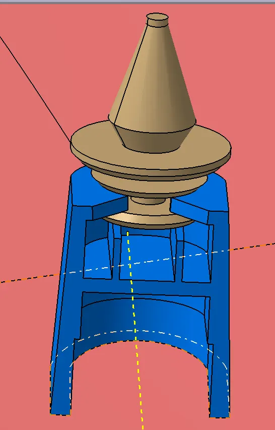
In this attachment feature created the dog house by using reference dimensions and by considering the main tool and side core axis. That is first drawed a sketch and then pad it into 28mm then extracted the outer surface and then offseted it into 2mm. then by using split command removed the inner portion. then again extraced that splitted inner surface and then offseted to 0.8mm with the height of 9.222mm from the bottom surface then by using split command removed that inner portion also then get a 1.2mm thicked part with the height of 1.2mm. then created ribs in dog house. Finally drafted along with side core axis. And then finally attached to lower substitute by using union trim command.
Push pin creation :-
The push pin is created by using pad and shaft cooamnds. And then finally placed on the dog house.
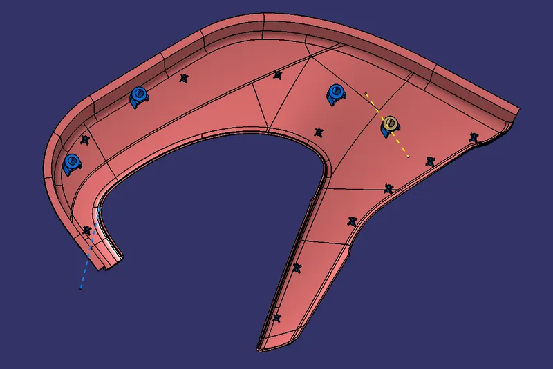
PART IMAGES :-
2. MAP POCKET 1 :-
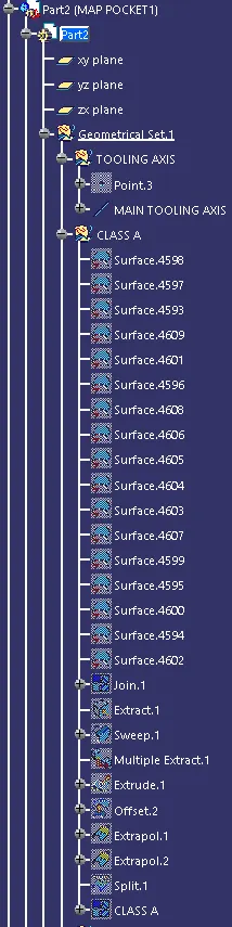
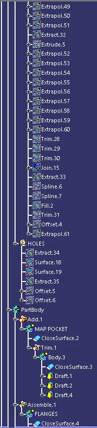
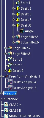
FEATURE TREE :-
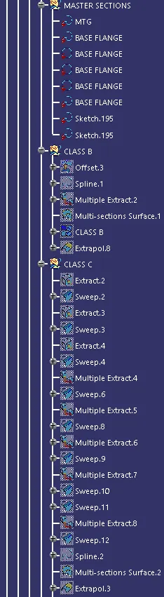
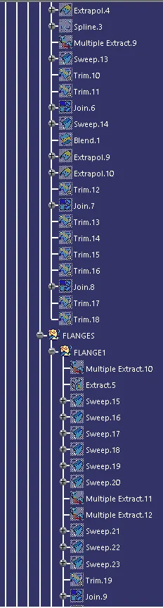
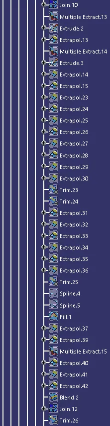
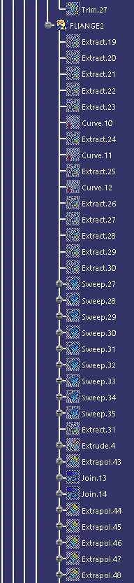
CLASS A :-
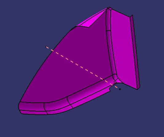
This class A is obtained by the joining of map pocket1 surfaces from the input surfaces. And here one flane is also created by using the swept command and the master section references. And then tooling aixs is created with normal to the surface.
CLASS B:-
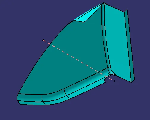
The below class B surface is created by the offsetting the class A surface for 2.5mm . The offset distance is obtained by the master section references.
CLASS C :-
The class C surrface is created by the swept coomand . The swept is created from the boundary of class A surface.
CLOSED BODY OF MAP POCKET1 :-
Finally by trimming the class A , class B and class C together we get a Closed body of map pocket1.
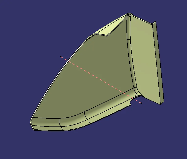
PART BODY :-
BY using close surface coomand the closed surface body get converted into part body.
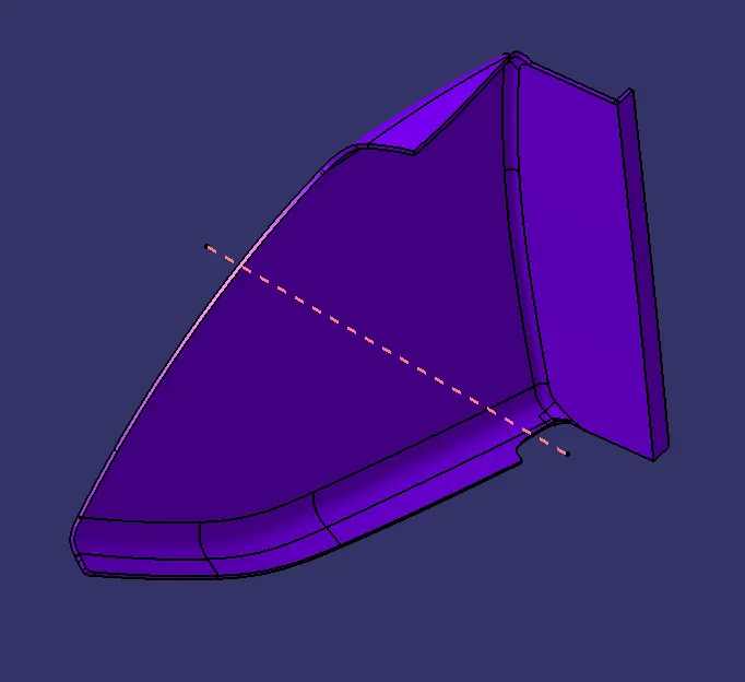
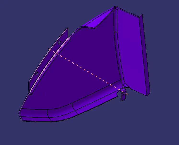
PART BODY WITH FLANGES :-
In this the flanges are created by using the references from the master sections and the swept coomands. And holes also created for heat stakes .
PART IMAGES :-
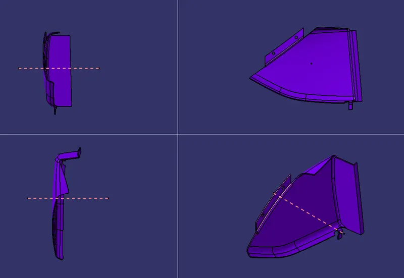
3. MAP POCKET :-
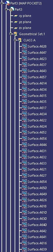
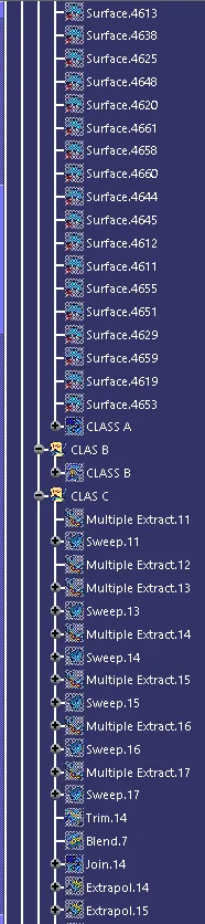
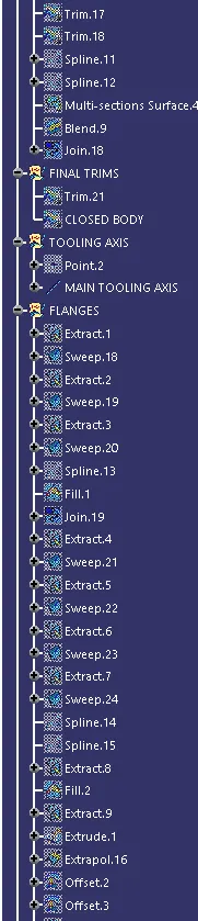
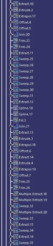
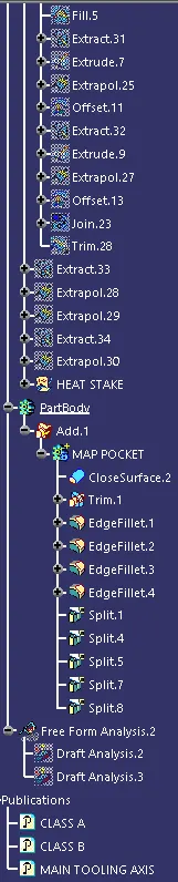
FEATURE TREE :-

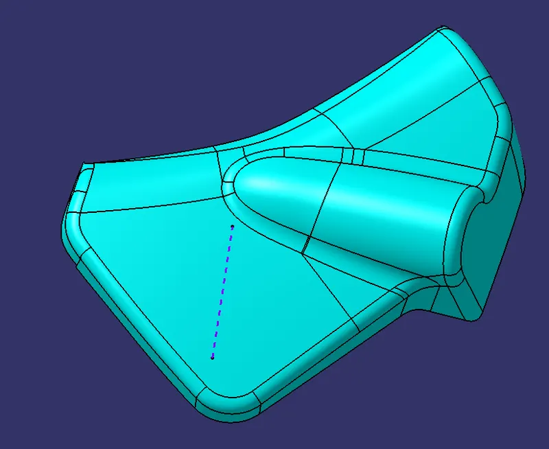
CLASS A :-
This class A is obtained by the joining of lower substitute surfaces from the input surfaces. And then tooling aixs is created with normal to the surface.
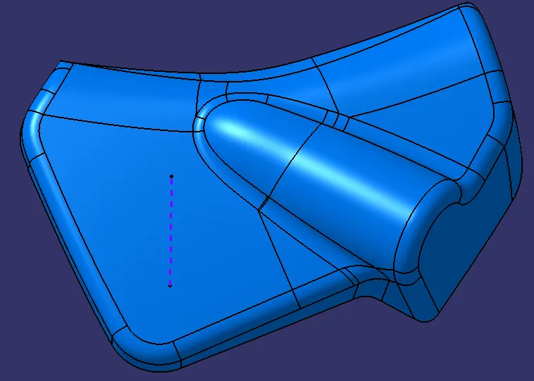
CLASS B :-
The below class B surface is created by the offsetting the class A surface for 2.5mm . The offset distance is obtained by the master section references.
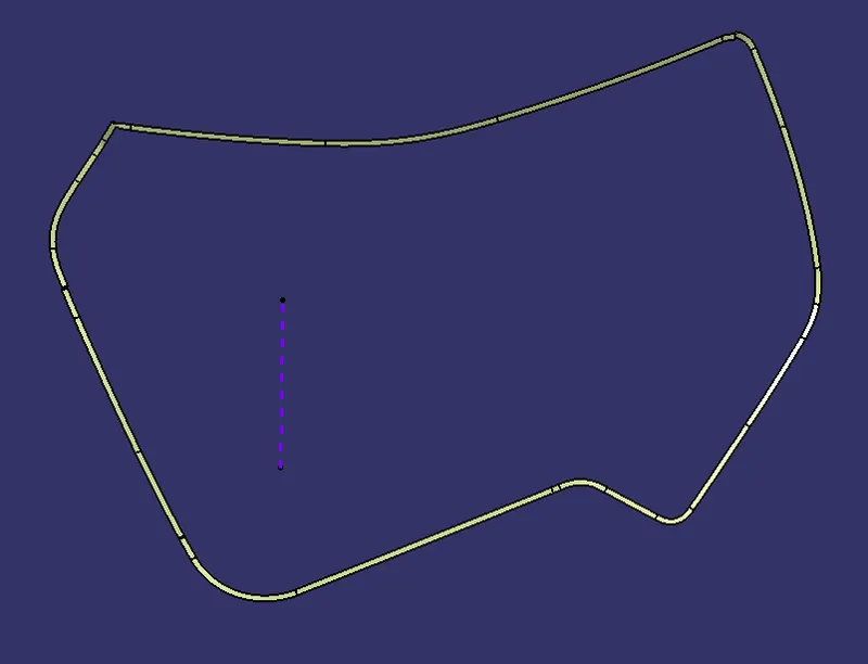
CLASS C OF MAP POCKET :-
The class C surrface is created by the swept coomand . The swept is created from the boundary of class A surface.
CLOSED BODY OF MAP POCKET :-
Finally by trimming the class A , class B and class C together we get a Closed body of map pocket2.
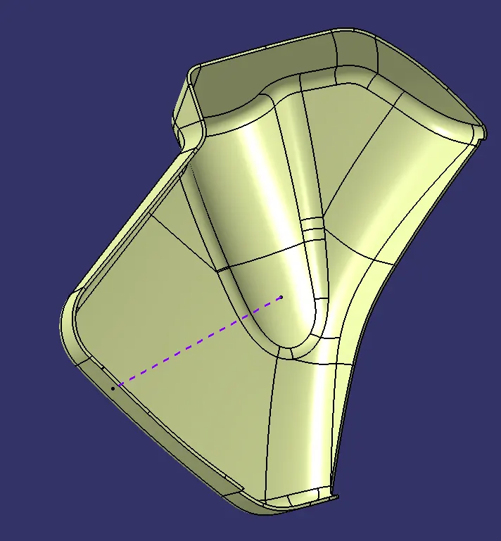
PART BODY OF MAP POCKET :-
BY using close surface coomand the closed surface body of map pocket2 get converted into part body.
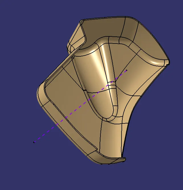
PART BODY OF MAP POCKET WITH FLANGES :-
In this the flanges are created by using the references from the master sections and the swept coomands. And the holes are created for the heat stakes.
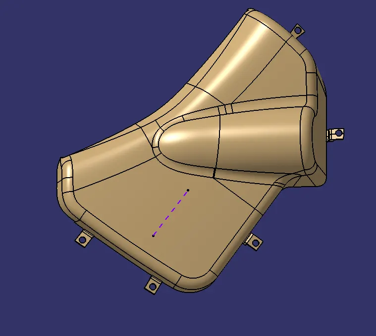
PART IMAGES OF MAP POCKET :-
3.DOOR ARM REST 1 :-
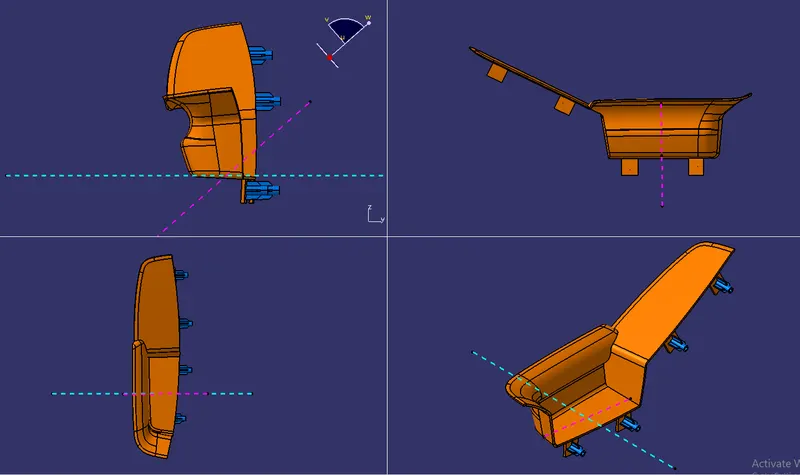
Actually door arm rest is a single component . but if it is in single component its impossible to manufaure. So split that door arm rest into two components.
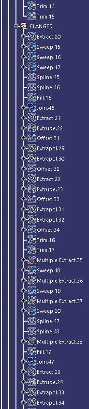
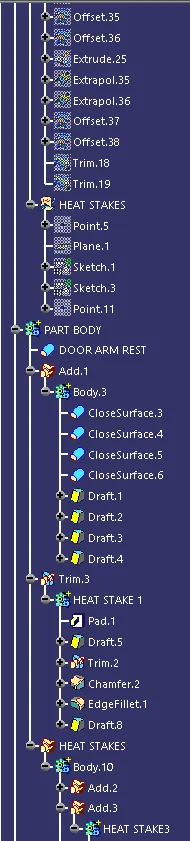
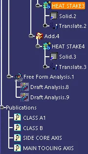
FEATURE TREE :-
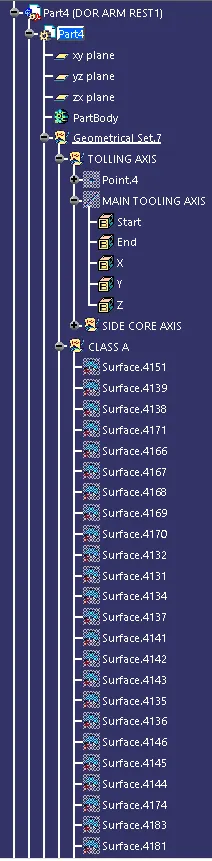
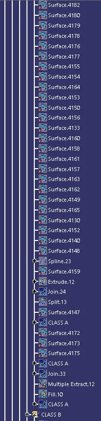
CLASS A :-
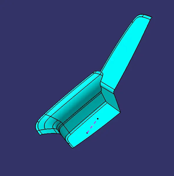
This class A is obtained by the joining of door arm rest1 surfaces from the input surfaces. And then tooling aixs is created by using compass direction method.
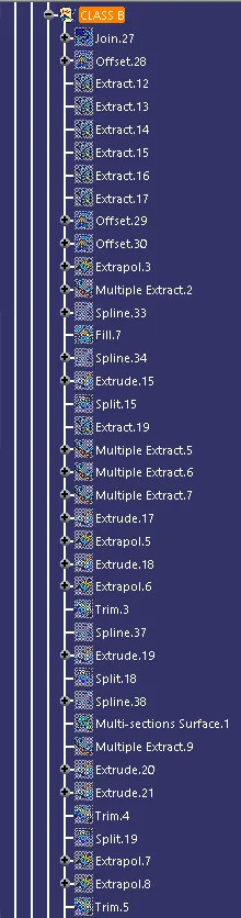
CLASS B :-
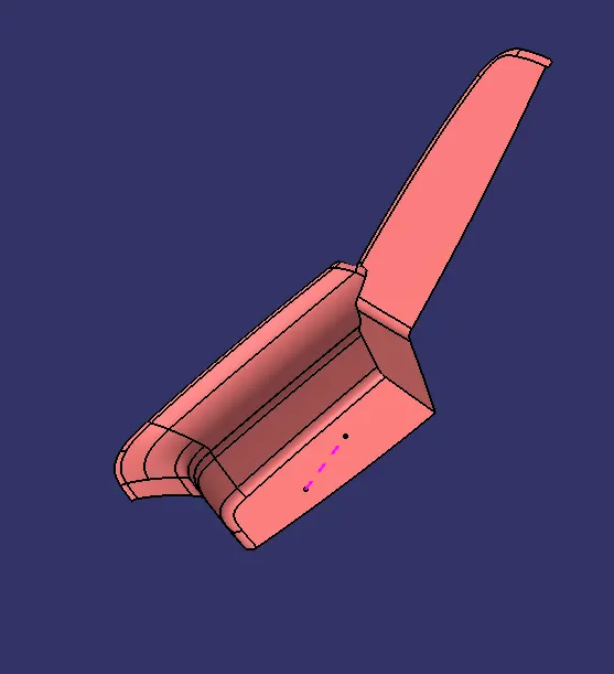
The below class B surface is created by the offsetting the class A surface for 2.5mm . The offset distance is obtained by the master section references. But here not the whole surface is not comes properly . there will some patches are coming. By using multisection surface coomands the patched surface is fills with material.
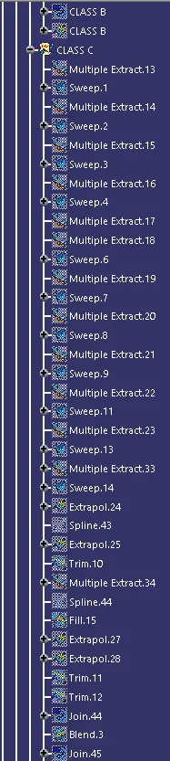
CLASS C :-
The class C surrface is created by the swept coomand . The swept is created from the boundary of class A surface.
CLOSED BODY :-
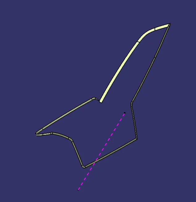
Finally by trimming the class A , class B and class C together we get a Closed body of door arm rest1.
PART BODY OF ARM REST :-
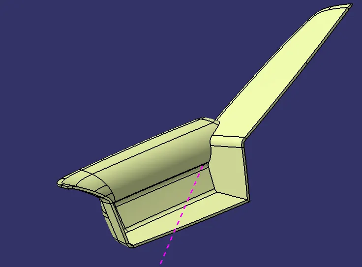
BY using close surface coomand the closed surface body of door arm rest is get converted into part body.
ARM REST WITH FLANGES :-
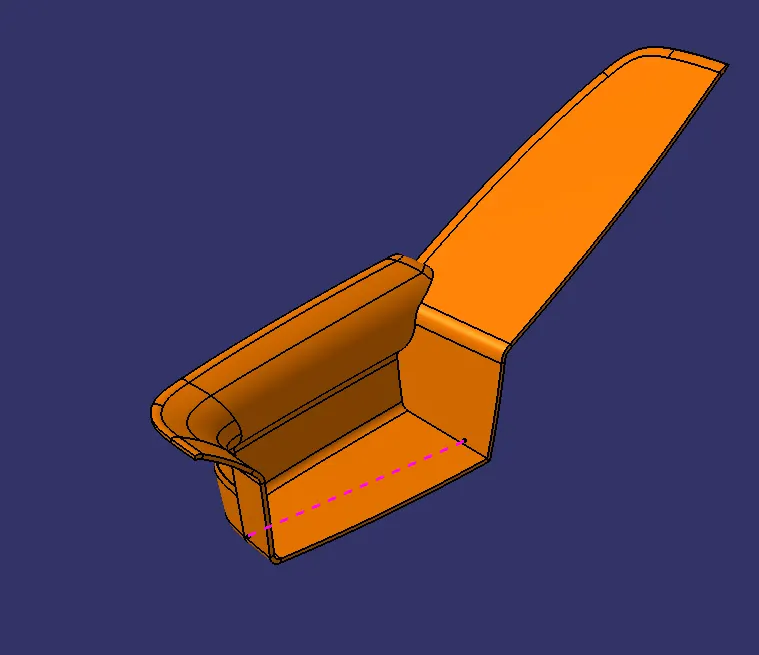
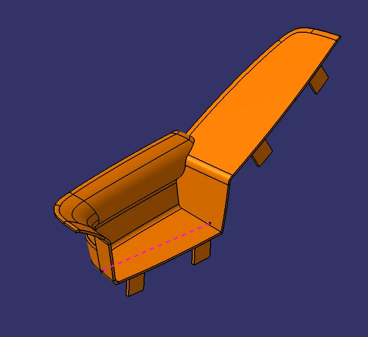
In this the flanges are created by the swept coomands for creating attachment features.
ARM REST WITH HEAT STAKES AND RIBS :-
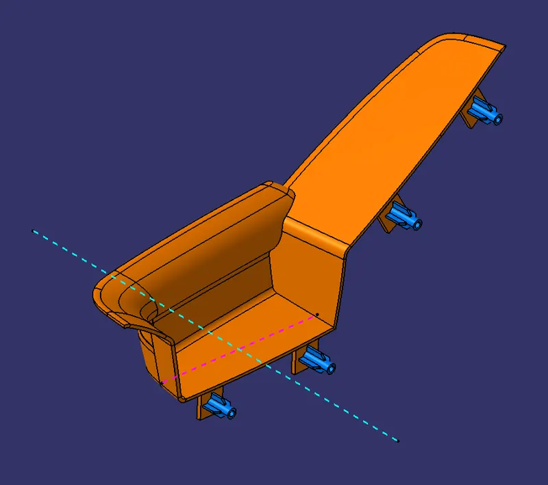
The heat stakes and ribs are created on surface of the flanges by following the design principles.
PART IMAGES OF ARM REST :-
5.DOOR ARM REST 2 :-
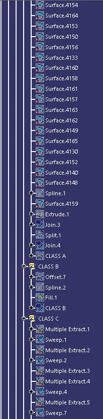
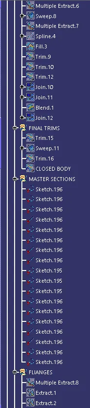
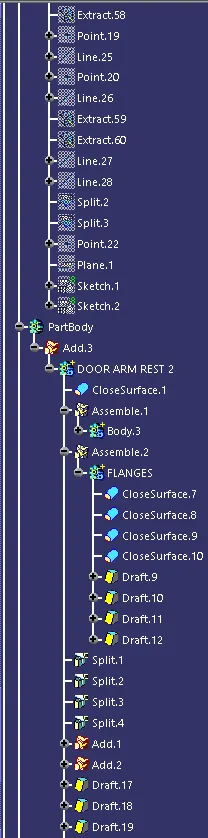
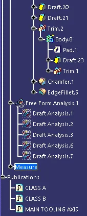
FEATURE TREE :-




CLASS A OF DOOR ARM REST :-
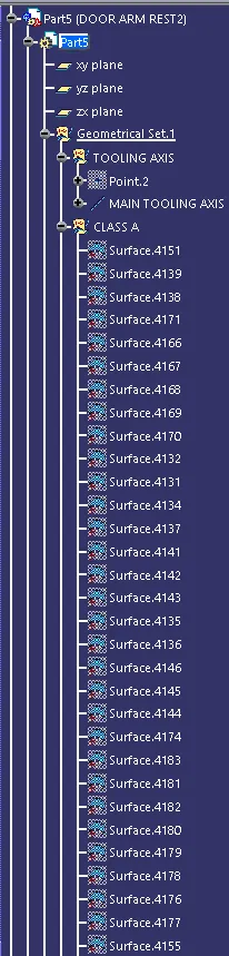
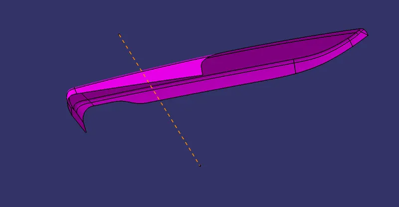
This class A is obtained by the joining of door arm rest2 surfaces from the input surfaces, then that joined surface is offsets to 2mm becacuse there will be a leather comes for appearance purpose. And then tooling aixs is created with normal to the surface.
CLASS B OF DOOR ARM REST :-
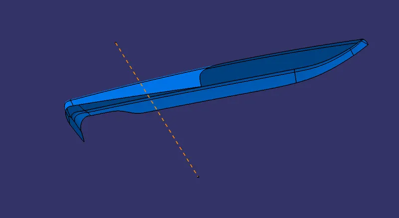
Here the class B obtained by offseting the offsetted class A into 2.5mm by using master section references.
CLOSED BODY OF DOOR ARM REST:-
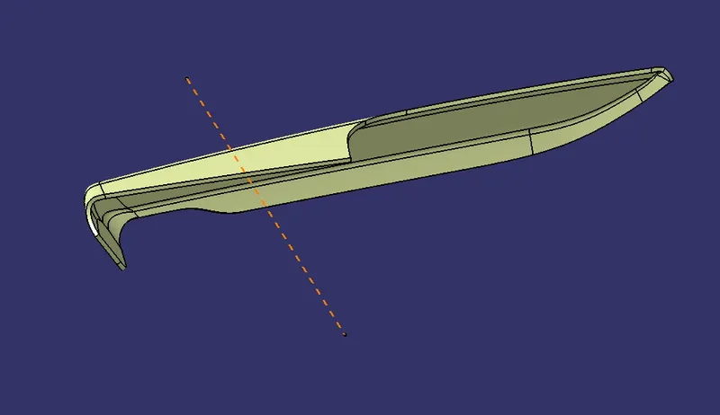
Finally by trimming the class A , class B and class C together we get a Closed body of door arm rest2.
PART BODY OF DOOR ARM REST :-
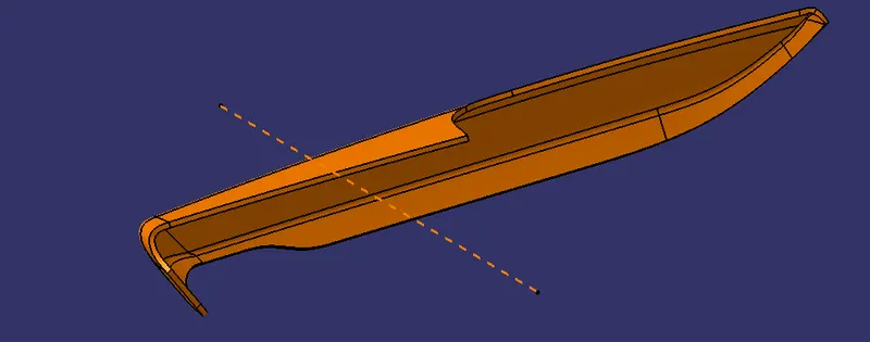
BY using close surface coomand the closed surface body of door arm rest2 is get converted into part body.
DOOR ARM REST WITH FLANGES :-
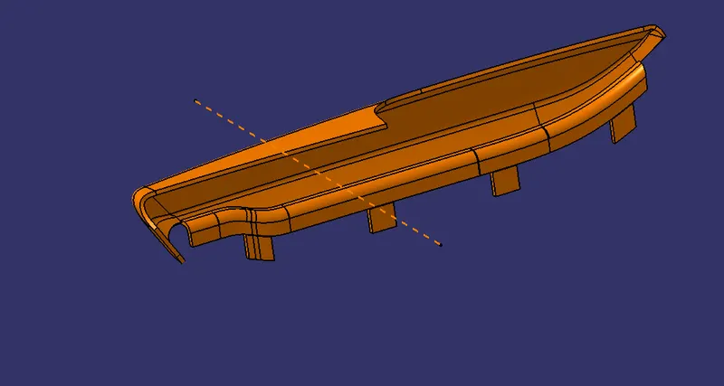
In this the flanges are created by using the references from the master sections and the swept coomands. And the holes are created for the heat stakes.
DOOR ARM REST WITH HEAT STAKES AND RIBS :-
In this the heat stakes and ribs are created by the reference of the master section. But the height given in master section is to high , so for satisfying the design rules decreased the height of it.
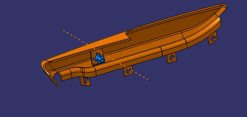
PART IMAGES OF DOOR ARM REST :-
ASSEMBLED DOOR TRIM PANEL MODEL :-
FEATURE TREE :-
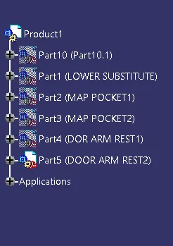
The below models are represented the assembly of Lower substitute, Map pocket1, Map pocket2, Door arm rest1 and Door arm rest2 .
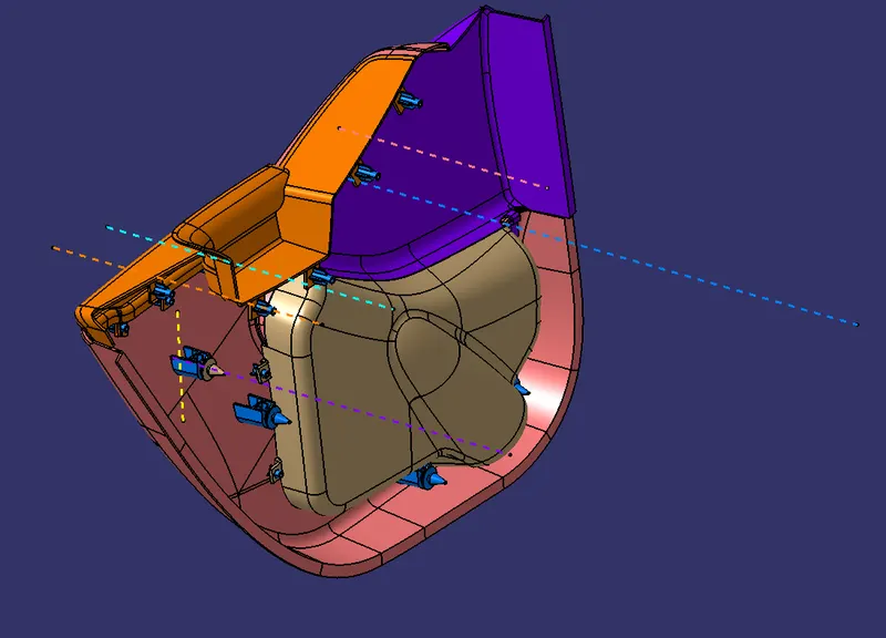
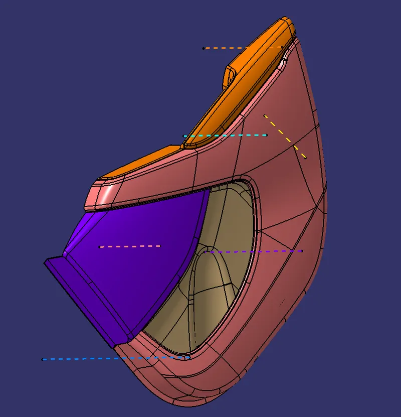
PART IMAGES :-
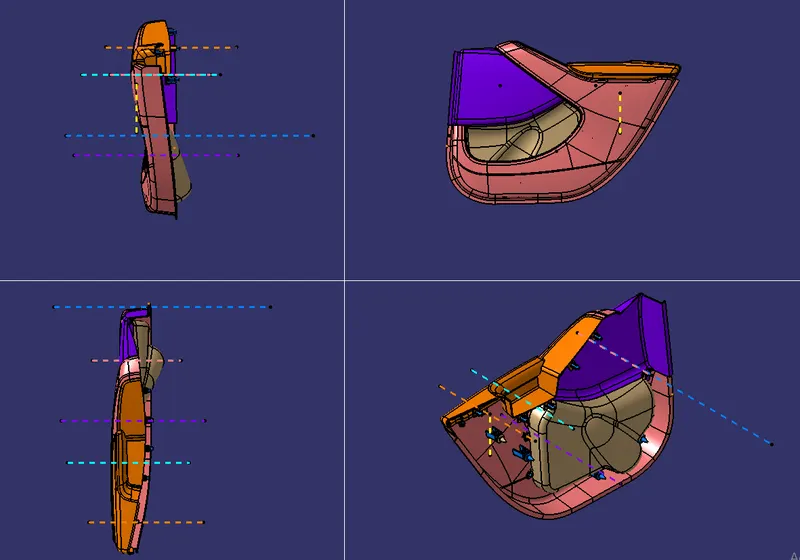
DRAFT ANALYSIS FOR ALL PARTS :-
1.DRAFT ANALYSIS OF LOWER SUBSTITUTE :-
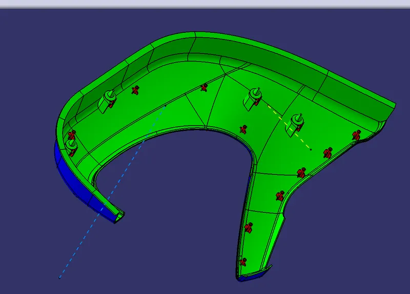
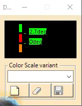
All areas are with minimum 3 degree draft except the ares are shown in the next slide .
class A :-
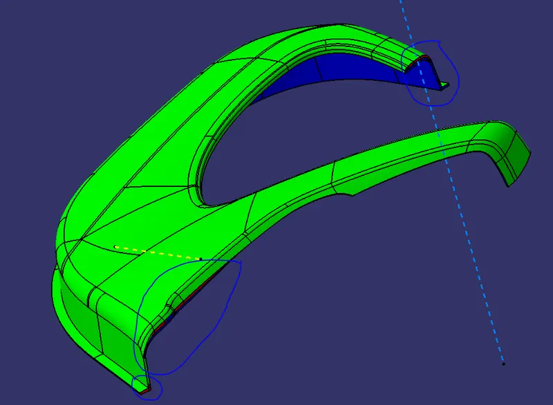
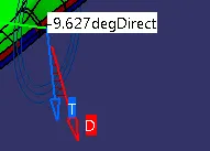
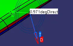
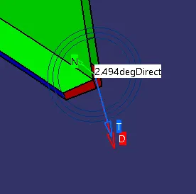
Min value at this area is -9.6deg Min value at this area is 0.9deg min value at this area is 2.4deg.
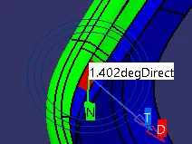
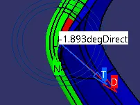
min value at this area is 1.4deg. min value at this area is -1.8deg.
class B :-
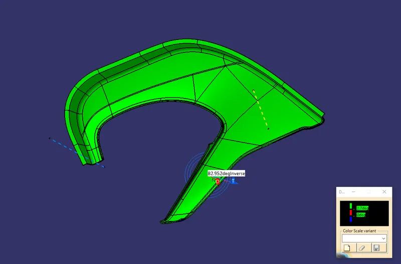
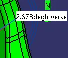
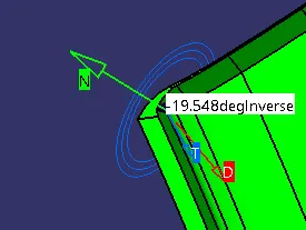
min value at this area is 2.6deg. min value at this area is -19.5deg.
class c :-
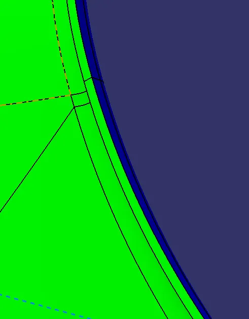
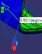
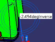
min value at this area is 0.9deg. min value at this area is -2.4deg.
HEAT STAKE DRAFT ANALYSIS :-
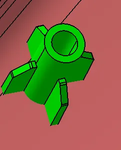
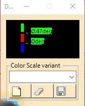
All faces are with min 0.5deg draft.
DOG HOUSE DRAFT ANALYSIS :-
1. With side core axis :-
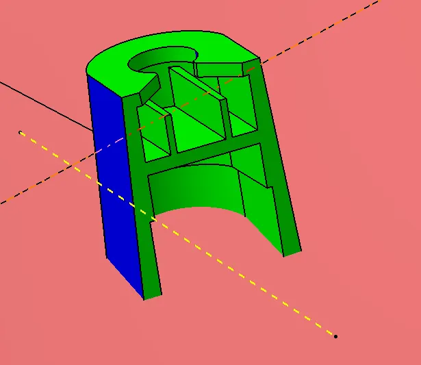
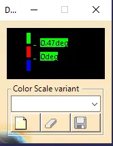
All faces are with min 0.5deg draft.
2. With main tooling axis :-
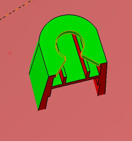
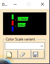
All faces are with minimum 3 deg draft.
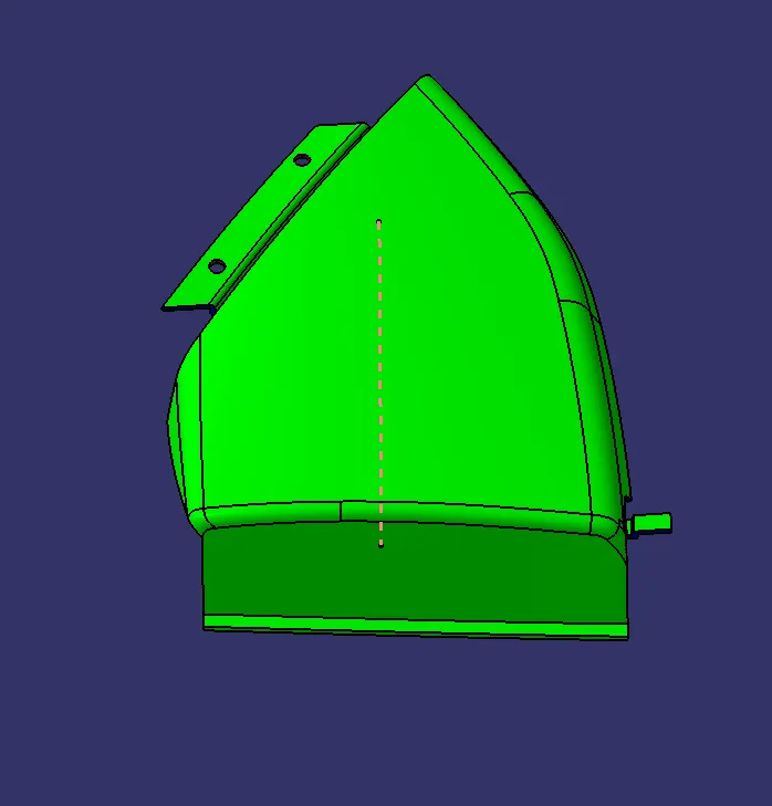
2.MAP POCKET 1 DRAFT ANALYSIS :-
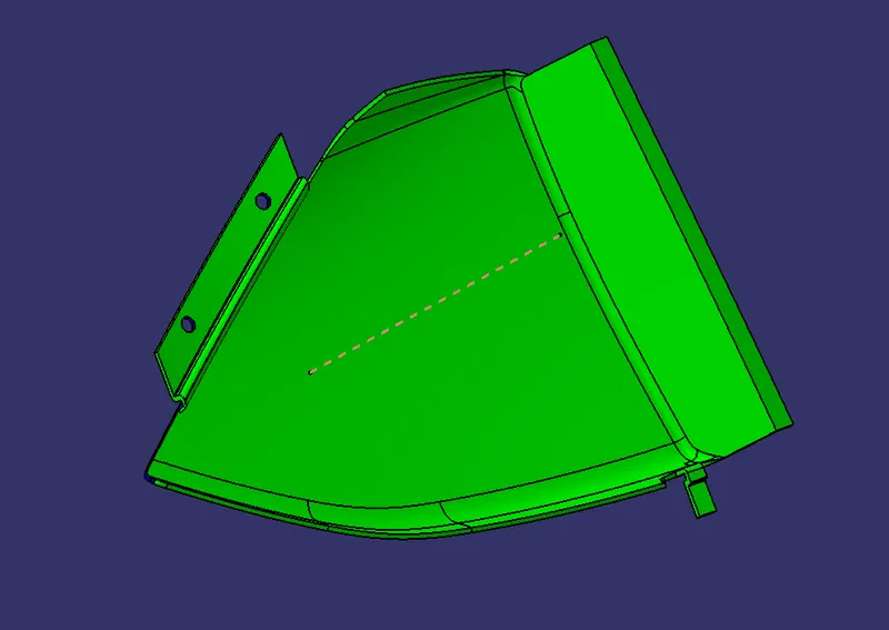
All faces are with minimum 3 degree except showing in the next slides .
class A :-
All faces of class A are with min 3 degree draft.
class B :-
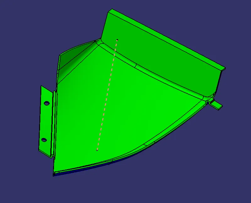
In this area all faces of class B are with min 3 degree draft.
CLASS C :-
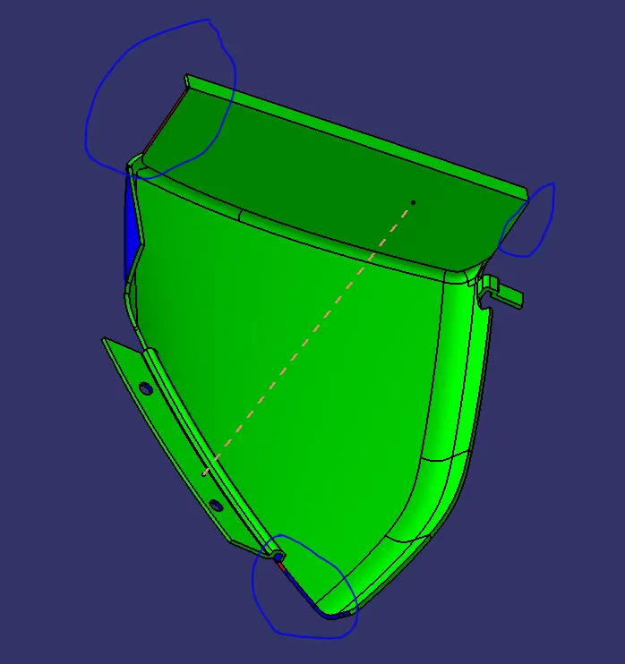
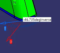
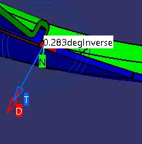
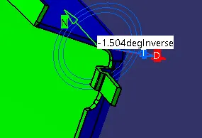
Min value at this area is -46.7deg. Min value at this area is 0.2deg. Min value at this area is -1.5deg.
3. MAP POCKET 2 DRAFT ANALYSIS :-
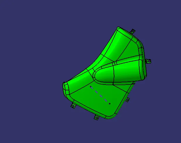
All faces are with minimum 3 degree except showing in the next slides .
CLASS A:-
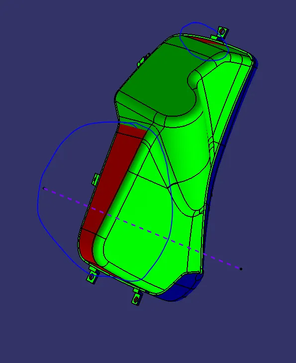
In this area the given class A is problem.
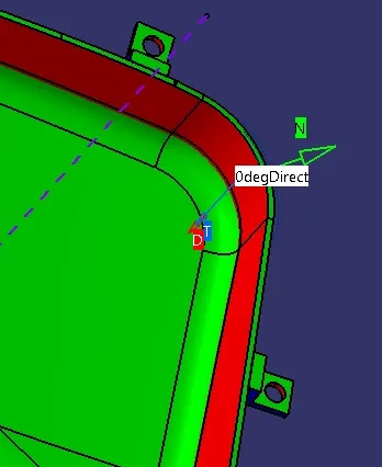
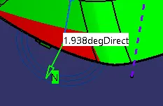
Min value at this area is 0 deg. Min value at this area is 1.9deg.
CLASS B :-
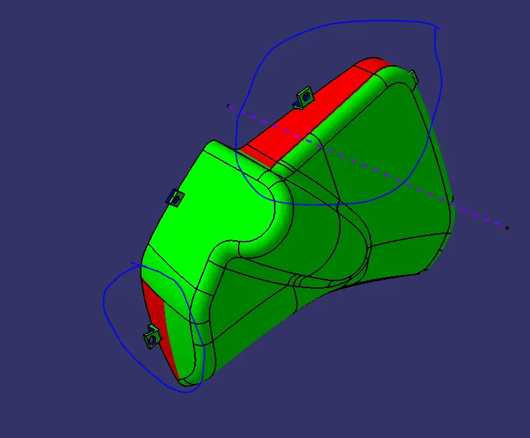
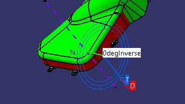
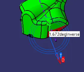
Min value at this area is 0 deg. Min value at this area is 1.6 deg.
CLASS C :-
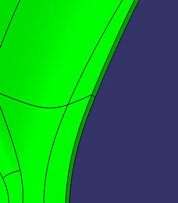
In this area all faces of class C are with min 3 degree draft.
4. DOOR ARM REST 1 DRAFT ANALYSIS :-
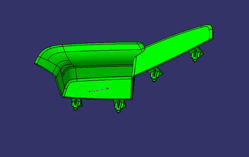
All faces are with minimum 3 degree except showing in the next slides .
CLASS A :-
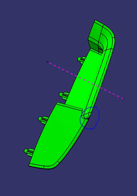
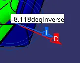
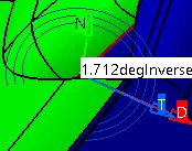
Min value at this area is -8.1deg. Min value at this area is 1.7deg.
CLASS B :-
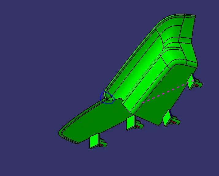
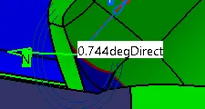
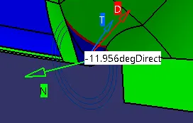
Min value at this area is 0.7deg. Min value at this area is -11.95deg.
CLASS C :-
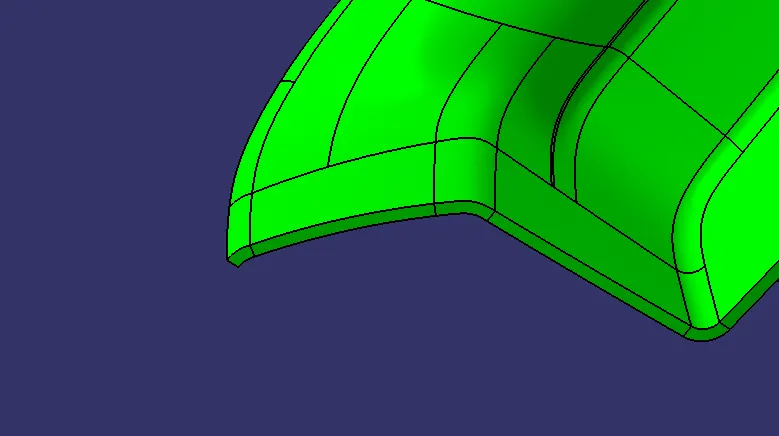
In this area all faces of class C are with min 3 degree draft.
DRAFT FOR HEAT STAKES BY SIDE CORE AXIS :-
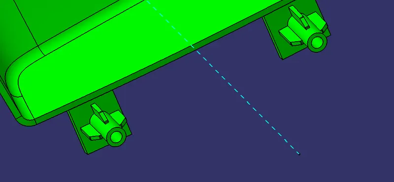
In this area all faces of heat stakes and ribs are with min 0.5 degree draft.
5. DOOR ARM REST 2 DRAFT ANALYSIS :-
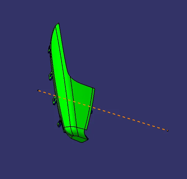
All faces are with minimum 3 degree except showing in the next slides .
CLASS A :-
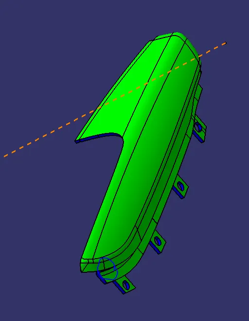
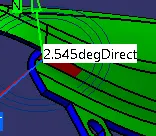
Min value at this area is 2.5 deg.
CLASS B :-
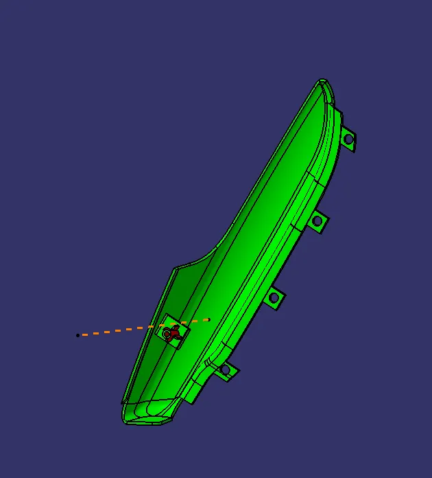
In this area all faces of class B are with min 3 degree draft.
CLASS C :-
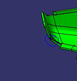
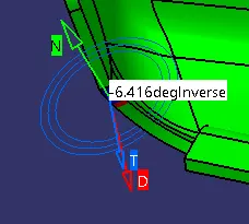
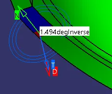
Min value at this area is -6.4deg. Min value at this area is 1.4deg.
HEAT STAKE DRAFT :-
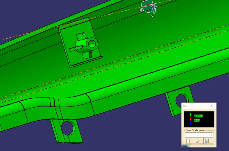
In this area all faces of class C are with min 0.5 degree draft.