Week 11 - Final project
OBJECTIVE
- Create The Door Trim Assembly From The Given A Surface
- Refer To The Master Section For Nominal Thickness, Flanges, and Heat Staking Placement
- Assemble the respective components into the single product
- Door Arm Rest
- Lower Substrate
- Upper Map Pocket
- Lower Map Pocket with Bottle holder
INPUT
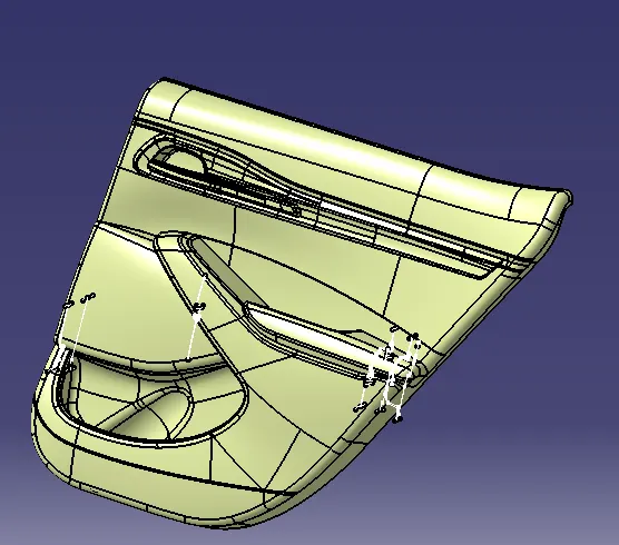
INTRODUCTION
Door Panel Serves as an interface between the interior of the car and the inner working of the door and between Vehicle Occupants and Door. They are expected to meet a variety of design specifications regarding safety, aesthetics, and functionality. In addition, they are expected to continue the material theme of the dashboard and pillars while concealing intricate electrical and mechanical components for operating locks, windows, and other features. The door panel has evolved from a simple two-part system of the latch and simple winding mechanism to a more sophisticated enclosure. Doors currently have an inner full-width panel consisting of electronic windows, a central locking system, and speakers. These panels typically consist of a foamed core covered with either textiles or plastics
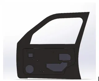
CLASS A SURFACE
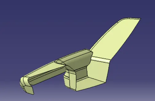
CLASS A is any of a set of freeform surfaces of high efficiency and quality. Although strictly, it is nothing more than saying the surfaces have curvature and tangency alignment – to ideal aesthetical reflection quality, many people interpret class A surfaces to have G2 (or even G3) curvature continuity to one another
A common method of working is to start with a prototype model and produce smooth mathematical Class A surfaces to describe the product's outer body. From this, the production of tools and inspection of finished parts can be carried out. Class A surfacing complements the prototype modeling stage by reducing time and increasing control over design iterations.
Class A surfaces can be defined as any surface, that has styling intent, that is either seen, touched or both and mathematically
CLASS B SURFACE
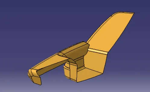
Class B surfaces are the secondary surfaces that you can see sometimes, but are less important, such as the inside of your glove box, ashtray, etc. These must be smooth and "error-free" as well but are not held to the standards that class A surfaces are.
CLASS C SURFACE
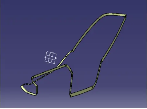
Class C surfaces are the backside surfaces that can have tool marks, flashes, and other imperfections without hurting appearance, function, etc
CONSIDERATION OF PROPERTIES FOR PLASTIC MANUFACTURABILITY
Designing a plastic part for manufacturability involves many important factors that touch on all areas of part design, tooling, material selection, and production. First, building parts around functional needs is essential by keeping design intent or the end-user in mind. Consider weight reductions, the elimination of fabrication and assembly steps, improving structural components, reducing costs, and getting products to market quicker. Here are 8 important factors to consider to meet your plastic part design goals for a successful production process.
- Material Considerations
Manufacturers often select a familiar grade of plastic from a similar application or rely on recommendations from suppliers. Resins chosen this way may be adequate but are rarely optimal. Plastic selection is a complex task that involves many considerations, such as:
- Temperature: Thermal stress that may occur during normal and extreme use conditions, as well as during assembly, finishing, and shipping.
- Chemical resistance: The effects that occur when any solid, liquid, or gas come in contact with the part.
- Agency approvals: Governmental and private standards for properties such as heat resistance, flammability, and electrical and mechanical capabilities.
- Assembly: The plastic’s cooperation with all assembly steps like bonding, mechanical fasteners, and welding.
- Finish: The material’s ability to produce the desired finish such as gloss, smoothness, and other appearance values as it comes from the mold.
- Cost: Resin pricing as well as the cost calculations for manufacturing, maintenance, assembly, and disassembly to reduce labor, tooling, finishing, and other costs.
- Availability: The resin’s availability regarding the amount needed for production.
- Radius
The radius should always be a consideration regarding the part’s thickness – eliminating the likelihood of areas of high stress and possible breakage of the part. A general rule of thumb is that the thickness at a corner should be in the range of 0.9 times the nominal thickness to 1.2 the nominal thickness of the part.
- Wall Thickness
Designing your part so that wall thickness is consistent can help avoid many part defects that can occur during the manufacturing process. When the plastic melts, it flows to the areas of least resistance. If your part has inconsistent thicknesses throughout, the melt may flow into the thick areas first (depending on gate locations). When this occurs, the thin areas may not fill properly. Additionally, thicker areas tend to cool more slowly and are at risk for voids or sinking defects. Designing your part with rounded corners will also aid in the proper filling of the part during the molding process.
- Gate Location
Gates are critical to ensuring the resin flows properly into the mold. These small components of your design are what direct the flow of resin from the runners to then be distributed through the part. The type of gate and placement has an important impact on the part’s overall quality and viability.
- Draft
A draft is the amount of taper on the vertical walls of the plastic part. Without a draft, a part may not eject from the mold or may sustain damage during ejection. Typically, draft angles between 1° and 2° are required but can vary depending on part restrictions and specifications.
- Inclusion of Ribs
A plastic part that has been designed with a minimal wall thickness will not be as strong as a thicker part – which is why the inclusion of ribs may be needed to help reinforce the part’s strength. Depending on the material used, rib thickness should be between 50 – 70 percent of the relative part thickness to avoid sink marks. To avoid sinking, designers may core out material to reduce defect risk.
- Mold Shrinkage
The shrinkage that occurs during the plastic part molding process can be as much as 20 percent by volume. Crystalline and semi-crystalline materials are most prone to thermal shrinkage. Amorphous materials are known to shrink less. Here are a few easy ways to avoid molding shrinkage issues:
- Adjust the formulation
- Adjust the mold design to get the dimension you want based on the expected shrinkage that will occur
- Optimize the processing parameters such as molding temperature, melt temperature, injection speed/pressure/time, and cooling time.
- Special Features
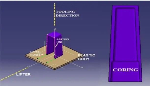
Plastic parts should be designed so that mold tools open and eject the part easily. When a part is released, the two sides of an injection mold separate in the opposite direction. When special features like holes, undercuts, or shoulders prevent the release from happening, it may be required that side actions be incorporated into the design.
Side actions pull coring in a direction other than the direction of the mold separation. This adds flexibility to the part design and at times, may increase the cost of the mold.
Working with an experienced plastic injection molder and engineering team is a critical component to avoiding many issues that can occur during the design and development process. If you keep these factors in mind during the design process and align with a knowledgeable plastics engineer, you will be on track to get your product to market quicker and within your budget.
ENGINEERING FEATURES
Engineering features are also termed as B-Side Features on Plastics. The different types of engineering features used in Door trims are
Dog house
Heat Stakes
Push clips
Rib Features
DOG HOUSE
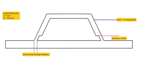
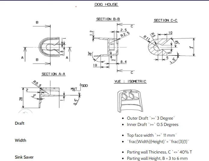
The dog house is an engineering feature used in the plastic trim design. Dog houses are used as supporting features. Sometimes other engineering features like snaps; locators, etc. are mounded on them to increase their strength. Dog houses are subjected to draft analysis to prevent breakage of the component during ejection from the mold cavity. Dog house and other engineering components are built on B-surface.
DOG HOUSE DESIGN GUIDELINES
HEAT STAKES
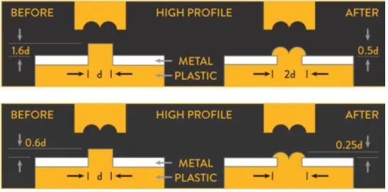
Thermal staking is an assembly method that uses the controlled melting and reforming of a plastic stud or boss to capture or lock another plastic or metal component of an assembly in place. The plastic stud protrudes through a hole in the component to be locked in place. The heated thermal tip contacts the top of the stud, which melts and fills the volume of the tip cavity to produce a head, locking the component in place. The progressive melting of plastic under continuous pressure forms the head. When staking, the right combination of heat and pressure for the application is critical
RIBS
Ribs are a feature in plastic injection molded parts. They are thin extensions that run perpendicular to a wall or plane. They are commonly used to provide additional support and strength to a part.
Thickness and location are essential to rib design. Here are some helpful design guidelines:
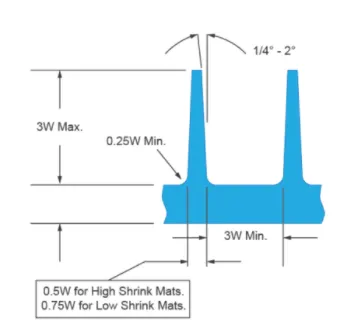
- They should be designed with a thickness that is ½ the wall thickness to avoid a thick section at the wall base
- To minimize sink marks, design ribs that are approximately 60% of the joining wall thickness for minimum risk
- Best practices include spacing at a distance of at least twice the wall thickness
- Glossy materials require a thinner rib (40% of wall thickness)
HEIGHT
Rib height should not exceed 3 times the thickness of the primary wall. This height cap is recommended because if your ribs are too tall, they can break during use or ejection from the mold. If damage occurs during the ejection of tall ribs, it is likely due to draft angles tapering them to slivers at their tips. Ideally, you want to keep your ribs as short as possible while still being functional.
WIDTH
Thick ribs can result in huge problems on your part. If a rib is too thick, the point where it attaches to the primary wall or boss will be thickened as well. This can easily cause sink marks, warp, and voids where there is this excess material. In particular, sinks are visible indicators of bad design, affecting your finished part's appearance. If severe enough, sinks and voids can reduce a part’s strength as they become concentrated centers of stress. To prevent these problems, it is recommended that your rib’s width fall between 0.5 and 0.75 times the primary wall’s thickness
RADII
The base of a rib should always be rounded with a radius to prevent an area of concentrated stress in the part. Sharp corners also hamper the plastic’s flow rate down into the rib, meaning it may not be able to fill before the material starts to cool, which will cause voids. For these reasons, a rib’s base should have a radius of end-user0.25-0.5 times the width of the primary wall, with the minimum radius being 0.010 inches.
SPACING
Even though multiple ribs add more support, you do not want to have so many that they crowd together. Ribs should be spaced no closer than their height, which is a maximum of 3 times the primary wall thickness. If ribs are closer than that, you run the risk of the ribs not being able to cool quickly. This means the part will have to stay in the mold longer before it can be ejected, which will increase your cycle time and your part cost. Another reason spacing is important is that ribs that are too close together will make it so there are thin sections of your mold. These are prime areas for damage to the mold to occur.
DRAFT
As with the majority of surfaces of injection molded parts, ribs must be drafted. The draft is especially important for ribs so that they can be removed without damage or breakage. A draft angle of 0.25-2 degrees, with 0.5-1 degrees being the most commonly used, should be applied to each side of the rib.
PUSH CLIPS
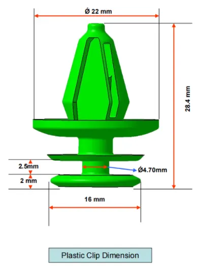
Push Clip is which connects the plastic part to the sheet metal and other parts of the body.
OPERATIONS UNDERGONE FOR CREATING DOOR TRIM MODEL
Door Arm Rest Model
Upper Map Pocket
Lower Map Pocket with Bottle Holder
Flanges
Heat Stakes with Ribs
Dog House
Push Clips
EXTRACTED SURFACE FROM DOOR TRIM INPUT
DOOR ARMREST
CLASS A
CLASS B
CLASS C SURFACE
CLOSED BODY WITH FLANGES
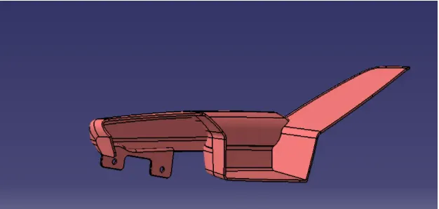
DRAFT ANALYSIS
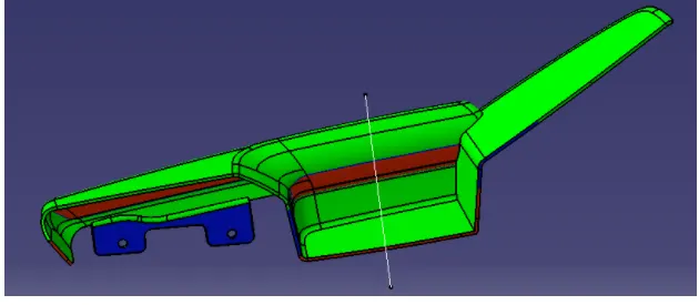
MAP POCKET
CLASS A SURFACE
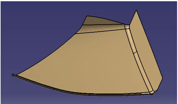
CLASS B SURFACE
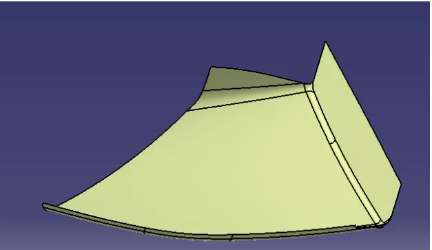
CLASS C SURFACE
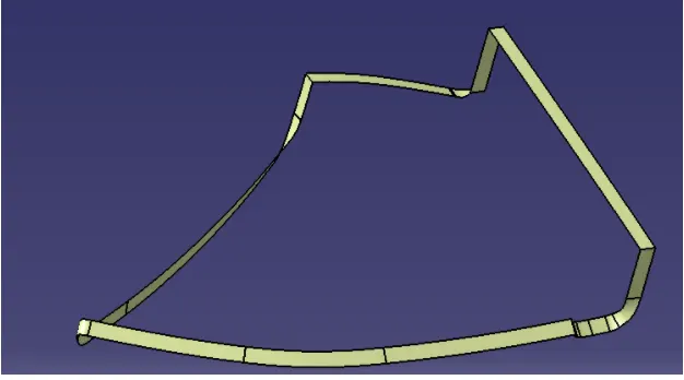
CLOSED BODY WITH HEAT STAKES AND FLANGE
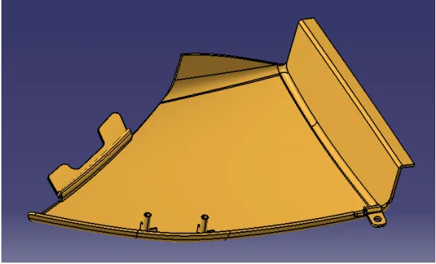
DRAFT ANALYSIS AND TOOLING AXIS
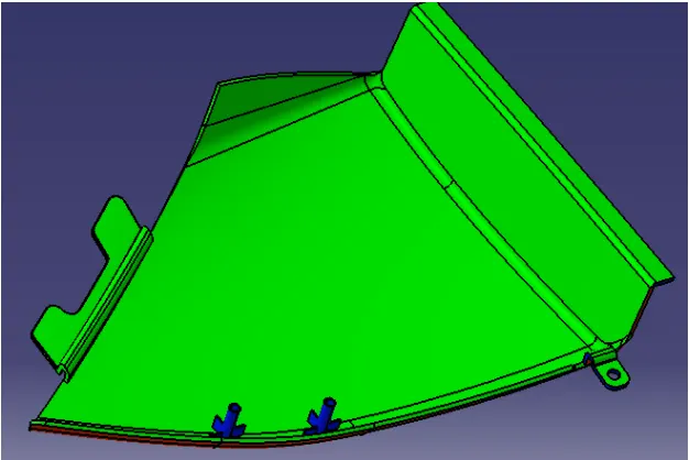
MAP POCKET WITH BOTTLE HOLDER
CLASS A SURFACE
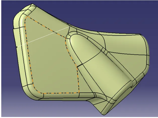
CLASS B SURFACE
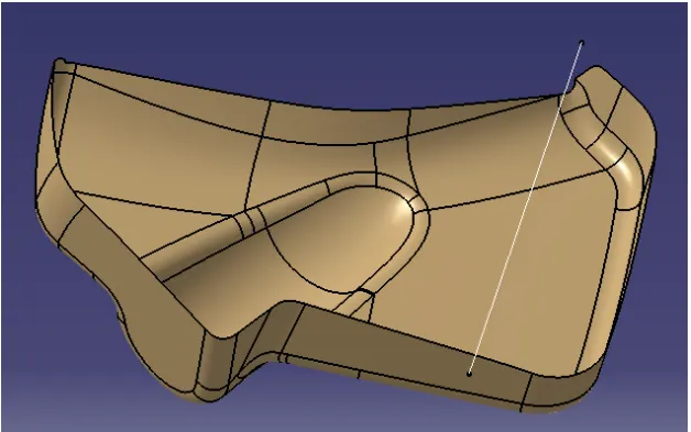
CLASS C SURFACE
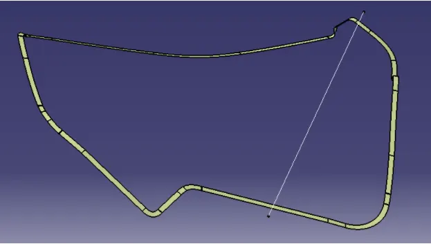
CLOSED BODY WITH FLANGES
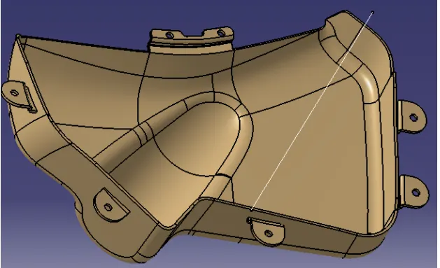
DRAFT ANALYSIS ALONG TOOL AXIS
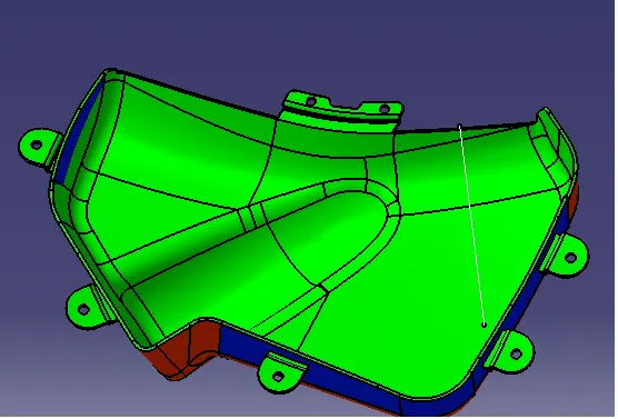
LOWER SUBSTRATE
CLASS A SURFACE
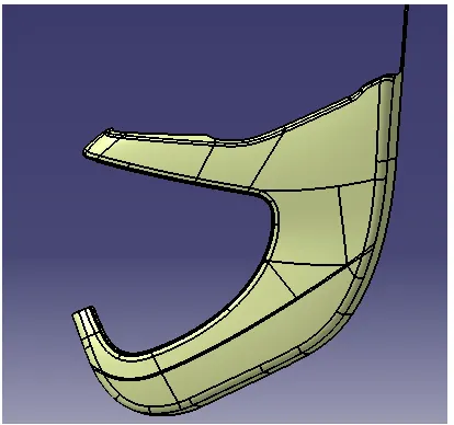
CLASS B SURFACE
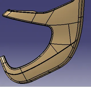
CLASS C SURFACE
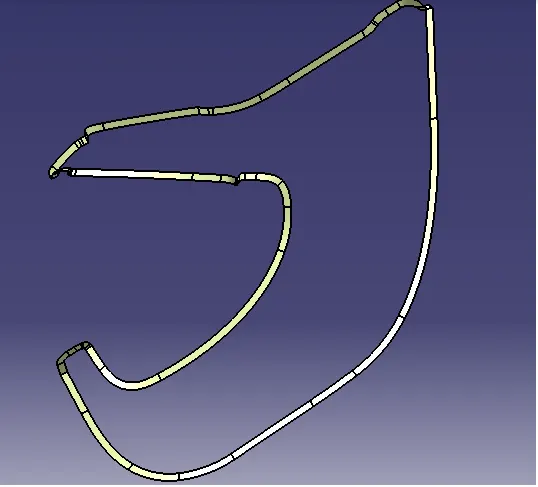
CLOSED BODY WITH HEAT STAKES AND DOG HOUSE
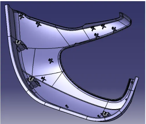
DRAFT ANALYSIS ALONG TOOLING AXIS
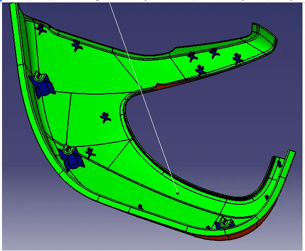
DRAFT ANALYSIS OF DOG HOUSE ALONG LIFTER AXIS
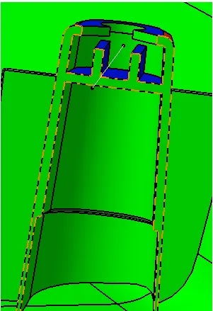
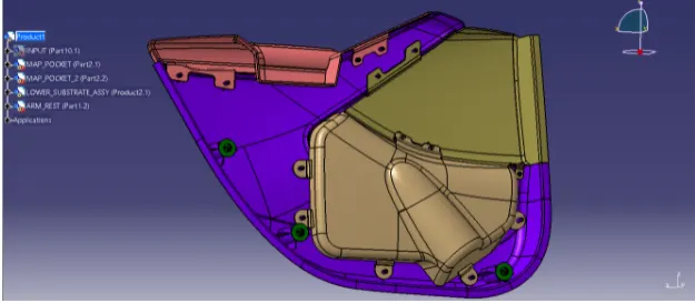
FINAL OUTPUT AND ASSEMBLY OF DOOR TRIM
CONCLUSION
HENCE THE GIVEN CLASS A MODEL HAS BEEN EXTRACTED AND CREATED AS PLASTIC COMPONENTS ALONG WITH ENGINEERING FEATURES CONSIDERING THE OEM STANDARDS
REFERENCE
1.https://www.sciencedirect.com/topics/engineering/door-panel
2.https://3space.com/blog/injection-molding-rib-design/
3.https://www.toolcraft.co.uk/injection-mould-tools/advice/injection-mould-tool-explained.htm