Week-11 Challenge: Braking
- For a defined driving cycle, calculate the energy required for braking.
- Why electric motor can’t develop braking torque at high speed similar to starting? How electric and mechanical brakes are coordinated?
- Make a MATLAB program which plots contour of given motor speed, torque and efficiency values. Attach the code as a .m file attach a screenshot of all the plots.
NOTE:
- Provide your Matlab code in the answer body itself.Paste the Screenshots of answer/plots/etc. in the answer body
- upload relevant files (excel, txt, mat, .xlm, .m whatever required).
- Add proper comments to the code wherever required for justification.
- Plagiarism (copy) will result in 0 grading (if beyond 70%). The TSE might ask on-the-spot questions to determine if the submission is yours or Not.
Aim:
Understanding the braking power and motor losses
Objective :
- For a defined driving cycle, calculate the energy required for braking.
- Why electric motor can’t develop braking torque at a high speed similar to starting? How electric and mechanical brakes are coordinated?
- Make a MATLAB program that plots the contour of given motor speed, torque, and efficiency values.
Introduction :
Regenerative braking :
The system captures kinetic energy during deceleration, storing it in the battery so it can be used as electricity to power the electric motor.
This is why conventional hybrids don’t need to be plugged in: they use regenerative braking to recharge their batteries as they’re being driven. Electric vehicles (EVs) run primarily off the charge they stored when plugged into an outlet, but use regenerative braking to help top up the battery.
In addition to the regenerative system, all electrified vehicles have conventional braking systems as regular vehicles do. These use metal discs, called rotors, that are located behind the wheels and which turn with them. When you press the brake pedal, the pressure of hydraulic fluid squeezes metallic brake pads tightly against the rotors, and the resulting friction slows the car.
That friction converts kinetic energy to thermal energy, and the brakes get hot. The heat dissipates – automakers design everything to cool very quickly, because hot brakes don’t work as well – and that energy is lost. The idea behind regenerative braking is to capture that otherwise wasted kinetic energy and put it to use, converting it to electricity.
One-pedal driving”
How much energy is captured can depend on how the system is configured. With some, the driver can decide how much regenerative braking to use, usually by moving the gearshift lever while slowing down. When more aggressive braking is selected, the system will capture and store more energy, but the vehicle will also slow down sooner, and in some cases, may come to a complete stop.
Automakers often refer to this as “one-pedal” driving. With practice, drivers may be able to get through heavy traffic by only using the throttle, accelerating enough to move ahead as needed, and then letting off the pedal and letting the regenerative braking make the stop.
Driving behavior determines energy captured
Hybrids generally get better fuel economy in city traffic than on the highway, and it isn’t always because of speed. They need regenerative braking to charge their batteries, but if you maintain a steady speed and don’t slow down on the highway, the battery is feeding the electric motor (which will either augment the gas engine or run the vehicle by itself, depending on driving conditions) without getting anything back from the regenerative system. When it gets too low, the battery stops working with the gas engine and instead siphons some of its power to recharge.
How much energy a regenerative braking system captures depends on several factors — the driver is one of the most important ones. It’s estimated that a system’s ability to capture energy can range from about 16 to 70 percent, and that’s all in how the vehicle is being driven.
Losses in the motors :
Copper Losses -
I2R">I2RI2R
, where R is the Armature resistance and we say that Torque is proportional to Current, this copper loss can be considered as where
is to take care of the resistance of brushes and also take care of flux and its effect.
Copper losses =Kc⋅T2">Kc⋅T2Kc⋅T2
Iron Losses - Iron Losses are nothing but Magnetic losses, which is denoted as, where the factor is based on the Magnetic field effect.
Permanent Magnets have constant Magnetic eld and this Iron loss is based on the value of and this is going to change
according to the Speed. Various Speeds have different values of Back EMF and that is going to affect the Iron Losses.
Iron Losses = Ki⋅ω">Ki⋅ωKi⋅ω
Windage Losses - This is a Mechanical or friction of Windage losses. This is based on the size of shape of Motor and the amount o
windage losses that the motor is going to experience.
Windage Losses =Kw⋅ω3">Kw⋅ω3Kw⋅ω3
Constant Losses - This is denoted as C.
Total Losses - The Total Losses are considering the above four losses and denoted as,
Total Losses = Kc⋅T2">Kc⋅T2Kc⋅T2+Ki⋅ω">Ki⋅ωKi⋅ω+Kw⋅ω3">Kw⋅ω3Kw⋅ω3+C
Governing equations:
Breaking Energy,
where,
For Motor Efficiency
where,
E=12⋅m⋅(Vf−Vi)">E=12⋅m⋅(Vf−Vi)E=12⋅m⋅(Vf−Vi)
where ,
E = Braking Energy
m = mass of the vehicle
Vf = Final Velocity
Vi = Initial Velocity
Efficiency :
η=PoutPIn">η=PoutPInη=PoutPIn
where,
Pout=T⋅ω">Pout=T⋅ωPout=T⋅ω
PIn=Pout+Culoss+Feloss+Wnd(loss)+Closs">PIn=Pout+Culoss+Feloss+Wnd(loss)+ClossPIn=Pout+Culoss+Feloss+Wnd(loss)+Closs
Losses :
Culoss=Kcu⋅ω2">Culoss=Kcu⋅ω2Culoss=Kcu⋅ω2
Feloss=KFe⋅T2">Feloss=KFe⋅T2Feloss=KFe⋅T2
Wnd(loss)=Kw⋅T3">Wnd(loss)=Kw⋅T3Wnd(loss)=Kw⋅T3
Pin = Input Power to Motor
Pout = Output Power of Motor
Culoss = Copper Losses
Feloss = Iron Losses
Winloss = Winding Loss
Closs = Conduction Loss
T = Torque of motor
Solutions :
1. Calculate the braking energy for the defined drive cycle :
Program :
% calculating the braking energy for Udds dricve cycle
clear
close
clc
%Loading data file
drive_cycle=xlsread('calculatingbreakingpower');
% Defining Time and Speed
t= drive_cycle(:,1);
s= drive_cycle(:,2);
m=1000; % mass of the vehicle
% Braking Energy
for i=1:1300
if s(i+1)< s(i)
BE(i)= 0.5*m*(s(i+1)-s(i))^2 ;
end
end
%Total Braking energy
TE = sum(BE)/1000
fprintf("The Total Braking Energy Required is %fKJ",TE)
% Plotting
figure(1)
subplot(2,1,1)
plot(t,s)
xlabel('Time')
ylabel('Velocity')
title('Drivecycle')
subplot(2,1,2)
plot(BE)
xlabel('Time')
ylabel('Braking Energy')
calculatingbreakingpower
Explanation :
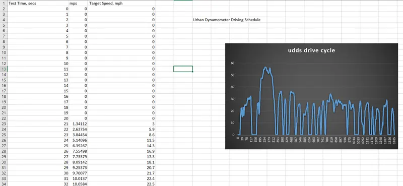
- Here we have used the predefined drive cycle of (UDDS) Urban Dynamometer Driving Schedule (UDDS) is commonly called the "LA4" or "the city test" and represents city driving conditions. It is used for light duty vehicle testing.
- The file was a Txt file which was later imported to excel file. The test contains was carried out for the total time of 1370 sec andd for which the speed was recorded in mph which was converted to m/s.
- Now to calculate the braking energy, we have used the Matlab program.
- In the first line, we have cleared all the values and plot using clear all close all and clc.
- Then the program starts with reading the excel file using the command the xlsread followed by the filename. This is definned by the variable drive cycle
- Later to read inputs of the file we have defined that 1 column of the excel sheet is the Time of the drive cycle and 2nd column of excel sheet is Speed of the drive cycle.
- Then we have defined the mass of the vehicle as 1000 kg
- We have applied a logic using the for loop and if condition that when the speed in the drive cycle is less than the previous data point speed, this means there is a brake applied.
- we calculate brake energy at this point using the above-mentioned kinetic energy formula and then after calculated all such braking energies we will add all of them and get total brake energy.
- The total brake energy is divided by 1000 to convert it into KJ and then used to printf command to print the final value.
- Lastly, we have used plot command to plot the graphs of the given data and the braking energy value. So the final value for the braking energy we get is 129.38 KJ
2.Why motor cannot develop braking torque at high speed
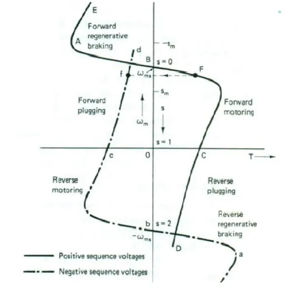
- The speed-torque curves obtained by the reversal of the phase sequence of the motor terminal voltages are also shown by dotted lines. With a positive sequence voltage across the motor terminals, the operation above synchronous speed gives the regenerative braking operation (portion BAE). Similarly, with a negative sequence voltage across the motor terminals, regenerative braking is obtained for speeds above the synchronous speed in the reverse direction (portion bae). In regenerative braking, the motor works as an induction generator, converting mechanical energy supplied by the load to electrical energy, which is fed to the source. Thus the generated energy is usefully employed.
- When we press the brake pedal, we cut off the power supply to the motor and now the motor will be in the rotation due to it inertia. As this rotation is happening inside the magnetic field a Back Emf is generated which produces a negative Torque and that used as the brakes to reduce the vehicle speed. Also the current flows in the reverse direction, Using a Bi-directional Inverter we can store the current back into the battery.
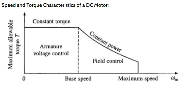
- During the initial low speed, the Torque is high which is the constant Torque region. As speed builds up, after the Critical spee point the torque gradually decreases which is known as the constant Power region.So during high speeds, the motor will be at constant power region, and while braking, due to the high speed of the motor the negative Torque produced will be less.
- But while starting the motor, the speed will be very less and at this stage, the motor will be operating in a constant Torque region and most of the torque is used to increase the kinetical energy of the load (and motor). But when the speed is already high and no extra load is applied it is not possible to increase the torque.
- There are other reasons like Battery Limitations due to which we cannot get High braking torque also the rate of discharge is always higher than the rate of charging due to the battery's chemical compositions.
Electric and mechanical brakes co-ordination :
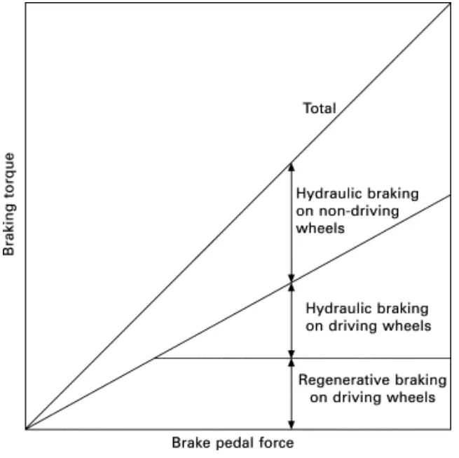
The braking stability of electric vehicles with electro-hydraulic hybrid braking systems can be influenced by braking force distribution between hydraulic braking force and regenerative braking force
Electric cars have regenerative braking and this does substantially reduce the need for hydraulic braking. But there are some limitations like the maximum deceleration with the engine alone is far smaller than with brake assistance So you still need an ordinary Fractional brake system to make the car stop instantly if required. * When the regenerative capacity is less than the actual braking required, mechanical brakes are applied at those times.
- During low brake pedal force, only the regenerative braking torque is applied on the driving wheels and is proportional to the pedal pressing force. The braking torque on the non-driving wheels is always due to hydraulic braking which is also proportional to the pedal pressing force.
- When the pedal force is beyond a certain limit, the maximum regenerative braking torque is applied on the driving wheels, and the hydraulic braking torque is simultaneously applied on the driving wheels to top up the desired braking torque. Meanwhile, the maximum regenerative braking torque is kept constant to fully recover the kinetic energy
There are two ways of applying the combination of brakes and they are classified as,
- Series - Regenerative braking and Frictional braking are applied one after another
Serial regenerative braking is basically based on the combination of friction-based adjustable braking system that transfers energ to the electric motors and batteries under an integrated control strategy. The overall design of serial regenerative braking is to estimate the deceleration required and distribute the required braking force between the regenerative braking system and the mechanical braking system. The serial braking system requires brake by wire system and has a more consistent pedal feel due to good torque blending capability. It can increase the efficiency by 15-30%.
2. Parallell - Regenerative braking and Frictional braking are applied at the same time . A parallel braking system is basically based on the combination of a friction-based system and the regenerative braking system operated in tandem without an integrated control. The regenerative braking force is calculated from the brake control unit b comparing the requested brake torque and the motor torque available. A parallel regenerative braking system requires more work in achieving good torque blending. This system can increase the efficiency by 9-18%.
One of the classic examples of coordination of these two brakes in the EDIIB, which is Electric Driven Intelligent Braking develop for the NISSAN leaf
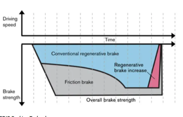
We see that both the Regenerative Brakes and the Frictional brakes are applied at the same time. After braking the speed reduces from higher speed values and at this moment the % of the composition of the combined braking changes. So after brake application, the speed is reduced to low speeds. Here Torque will be high and the motor will be operating in a constant Torque region. Now at this point, the % of Frictional brake application is reduced and Regenerative Braking is Increased because at this point more Negative Torque can be generated and thus higher electric power generated out of this braking can also be fed back to the battery. Thus using this technology in Braking an electric driven vehicle certainly increases the stopping power and also contributes to higher efficiency figures.
3. MATLAB program which plots contour of given motor speed, torque, and efficiency values
Program :
%motor charactersistcs
%speed_vs_torque_vs eficciency
clear all
close all
clc
w = linspace(0,1000); %speed of the motor
t= linspace(0,250); %torque
%Motor Losses
%for copper loss
k_c = 0.2;
%for iron loss
k_i = 0.008;
%for winding loss
k_w = 0.00001;
% constant loss
cl = 20;
% Making 2d matrix
[W,T] = meshgrid(w,t);
% Output power = torque*Speed
Out_power = (T.*W);
% Copper Loss
b = (T.^2)*k_c;
% Winding Loss
c = (W.^3)*k_w;
% Iron Loss
d = W*k_i;
% Input Power
In_power = Out_power +b +c +d +cl;
% Efficiency
E= Out_power./In_power;
%Efiiciency levels for contour
e=[0.70,0.75,0.80,0.82,0.87,0.89,0.90,0.92];
%plotting the graph
%Creating Contour
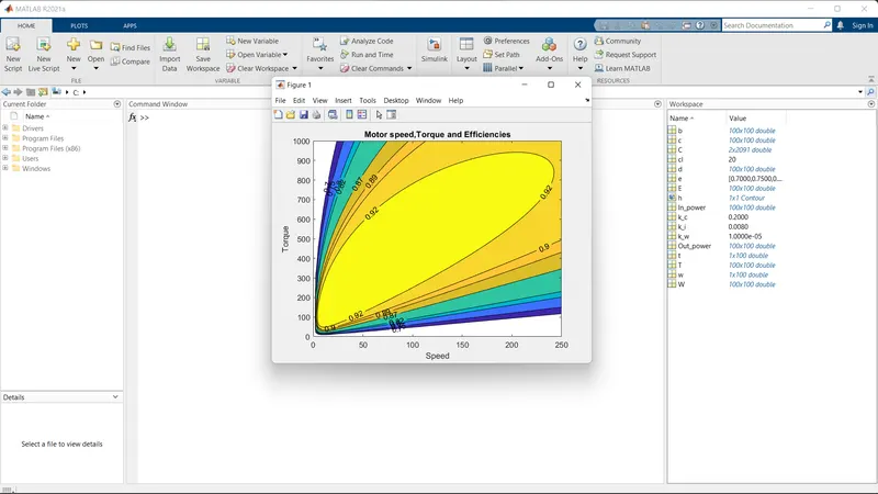
[C,h]=contourf(T,W,E,e);
clabel(C,h,'labelspacing',300); % plotting the effeciency values and its scpacing
xlabel('Speed');
ylabel('Torque');
title('Motor speed,Torque and Efficiencies')
Explanation :
- The program starts with assigning Input of Speed and Torque in an array using 'linspace' Command and allocate Constant Values for four losses(Copper Loss, Iron Loss, Windage Loss and Constant Motor Loss)
- Mesh the Speed and Torque values using 'meshgrid' command. Basically it makes the size of both array equal.
- Calculate the Output Power by multiplying Speed and Torque values.
- Calculate Copper Loss, Iron Loss, Windage Loss using those formulas.
- Calculating Inputpower by adding Output Power and Four Losses(Copper Loss, Iron Loss, Windage Loss and Constant Motor Loss).
- The ratio of Output Power and Input Power we can get the Efficiency.
- Now Set the Efficiencies for which a contour will be plotted. The range of contour efficiency is to plot Plot the Contour Efficiency using 'contour' command and plot Speed,Torque,Efficiency and V.'contour(X,Y,Z)' specifies the x and y coordinates for the values in Z. Contourf(Z) creates a filled contour plot containing the isolines of matrix Z, where Z contains height values on the x-y plane.
- clabel(C,h) labels the current contour plot with rotated text inserted into each contour line. The contour lines must be long enough to fit the label, otherwise clabel does not insert a label.
- Now the below plot shows the Motor Speed-Torque Efficiency Contour Plot with increasing efficiency order as going inward and decreasing efficiency order as going outward