Project 1
Design and Develop a PWM controlled fan load with DC motor
Ans:-
By controlling the electrical parameter of motor result in change of speed of Fan. Fan connected on shaft of the DC motor.
A DC motor consist basically of two parts, the stationary body of the motor called the “Stator” and the inner part which rotates producing the movement called the “Rotor”. For D.C. machines the rotor is commonly termed the “Armature”.
Generally, in small light duty DC motors the stator consists of a pair of fixed permanent magnets producing a uniform and stationary magnetic flux inside the motor giving these types of motors their name of “permanent-magnet direct-current” (PMDC) motors.
2-Pole Permanent Magnet Motor
As the armature rotates electrical current is passed from the motors terminals to the next set of armature windings via carbon brushes located around the commutator producing another magnetic field and each time the armature rotates a new set of armature windings are energised forcing the armature to rotate more and more and so on.
So the rotational speed of a DC motor depends upon the interaction between two magnetic fields, one set up by the stator’s stationary permanent magnets and the other by the armatures rotating electromagnets and by controlling this interaction we can control the speed of rotation.
The magnetic field produced by the stator’s permanent magnets is fixed and therefore can not be changed but if we change the strength of the armatures electromagnetic field by controlling the current flowing through the windings more or less magnetic flux will be produced resulting in a stronger or weaker interaction and therefore a faster or slower speed.
Then the rotational speed of a DC motor (N) is proportional to the back emf (Vb) of the motor divided by the magnetic flux (which for a permanent magnet is a constant) times an electromechanical constant depending upon the nature of the armatures windings (Ke) giving us the equation of: N ∝ V/KeΦ.
PWM Method
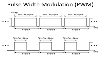
As its name suggests, pulse width modulation speed control works by driving the motor with a series of “ON-OFF” pulses and varying the duty cycle, the fraction of time that the output voltage is “ON” compared to when it is “OFF”, of the pulses while keeping the frequency constant.
The power applied to the motor can be controlled by varying the width of these applied pulses and thereby varying the average DC voltage applied to the motors terminals. By changing or modulating the timing of these pulses the speed of the motor can be controlled, i.e., the longer the pulse is “ON”, the faster the motor will rotate and likewise, the shorter the pulse is “ON” the slower the motor will rotate.
In other words, the wider the pulse width, the more average voltage applied to the motor terminals, the stronger the magnetic flux inside the armature windings and the faster the motor will rotate and this is shown below.
Pulse Width Modulated Waveform
The use of pulse width modulation to control a small motor has the advantage in that the power loss in the switching transistor is small because the transistor is either fully “ON” or fully “OFF”. As a result the switching transistor has a much reduced power dissipation giving it a linear type of control which results in better speed stability.
Also, the amplitude of the motor voltage remains constant so the motor is always at full strength. The result is that the motor can be rotated much more slowly without it stalling.
This Shows the work for the design of the fan speed control system using Pulse Width Modulation by establishing a connection between an H bridge circuit and a Dc motor. A fan type load equation has been used to analyze the output results instead of a physical model of a fan in Simulink. The speed of the fan is varied according to the input voltage using PWM technique.
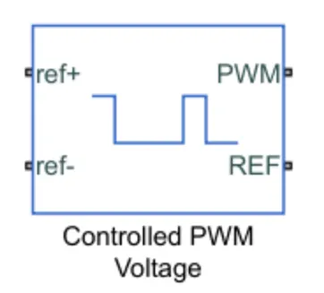
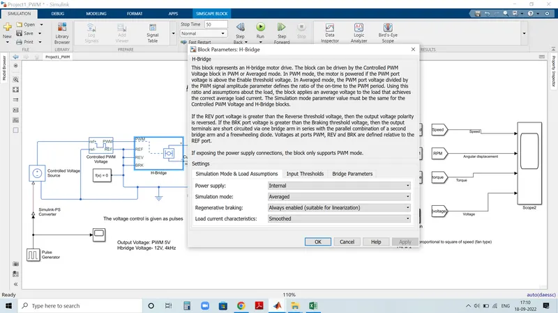
By changing or modulating the timing of these pulses the speed of the motor can be controlled. A stepwise change in the speed variation is given and the full load speed is observed. In this model, all input ports of the H-Bridge block except the PWM port are connected to ground. As a result, the H-Bridge block behaves as follows:
- When the motor is on, the H-Bridge block connects the motor terminals to the power supply.
- When the motor is off, the H-Bridge block acts as a freewheeling diode to maintain the motor current.
Model Diagram in Simulink
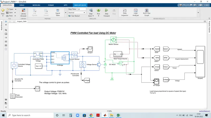
Model Explanation:
Torque exerted by fan represented by T
Load torque i.e. T proportional to square of speed i.e. w^2
T= K . w^2
By varying the electrical parameter of motor i.e. voltage and current we are controlling load torque or load speed.
For fan load we don’t have any block to represent a fan so we are representing by a subsystem
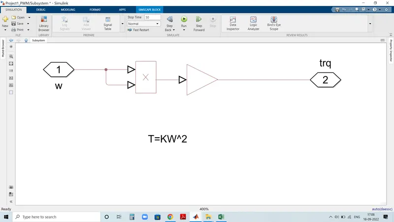
to the right side there is w and it is multiplying by product block then it is become w^2
Then gain block is used that is the constant of proportionality 8.8e-8 Unit of this gain block is N*m/(rad/s)^2
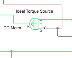
Output of this subsystem is fed to the Aerodynamic block. Actual name of this block is Ideal torque source block. This ideal torque source block is going to apply torque on the shaft of DC motor.
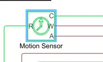
For getting the speed we used Motion sensor.Value of the motion sensor w is given to the subsystem w and the value of the torque is given to the aerodynamic block and therefore completing the loop.
Controlled voltage source is connected to the controlled PWM voltage and H-bridge is connected through PWM voltage.
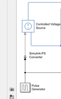
Pulse generator block used as input to the controlled voltage source.
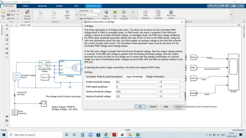
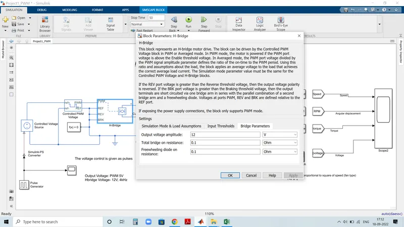
Parameters of H bridge block is as shown below images
Output Result of XY Graph
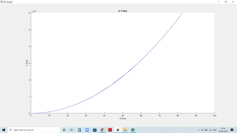
This xy-graph is the speed torque graph shows that Load torque proportional to square of speed
Output result of scope
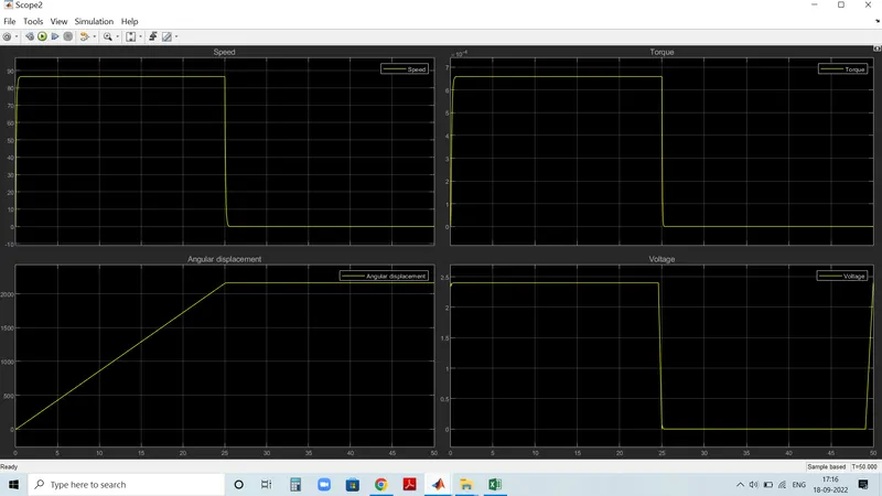
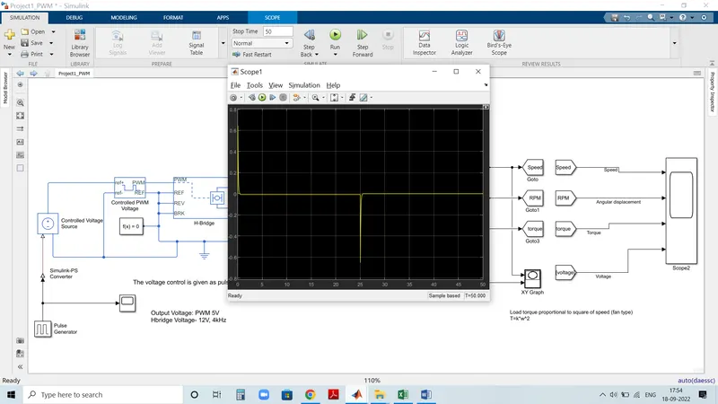
from the scope block sees that voltage is change with respect to pulse duty ratio by this speed is increases & in square proportion torque increases. The angular displacement also increases in step see in the scope waveform.
Current waveform
Conclusion-
From the above model and from the assumed parameters we found that the speed, Torque & angular displacement of a fan is shown in scope waveform matches with desired response.
A PWM-controlled DC motor using an H bridge circuit was modelled in Simulink and results were analysed. The output plots justified the theory discussed. The load torque characteristics of a fan is obtained.