Project - Speed Control of a Direct Current (DC) motor
Aim- Simulink model for the DC motor
The Speed control of a DC motor is either done manually by the operator or by means of an automatic control device.
This is different to speed regulation where the speed is trying to be maintained or regulated against the natural change in speed due to a change in the load on the shaft
speed can be varied by changing:
- The terminal voltage of the armature V
- The external resistance in armature circuit Ra
- The flux per pole
Terminal voltage and external resistance involve a change that affects the armature circuit while flux involves a change in the maginetic field
Therefore speed control of DC motor can be classified into:
- Armature Control Methods
- Field Control Methods
Mathamatical Model=
(ω(s))/(Vs(s))=(Kt)/(J*La*s^2+(J*Ra+B*La)*s+(B*Ra+kt*km))
Control design Objective-
- Design feedback control law u=-kx such that state x is driven to origin form any non zero initial condition OR regulate around set point starting form zero initial condition OR track given referance command starting from zero initial condition.
Simulink model :
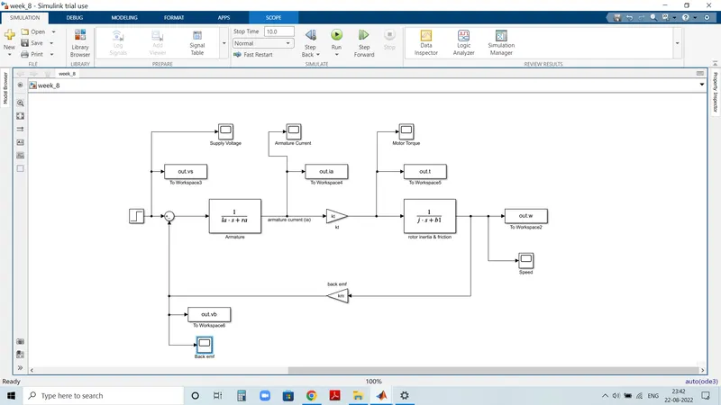
- we need to creat simulink model of the DC motor and make it as subsytem called the DC motor
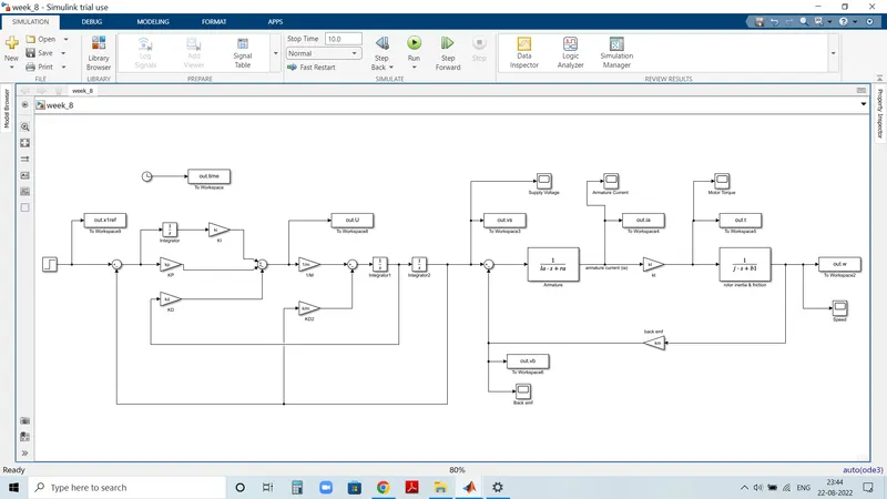
- So next the subsytem of DC motor is connected to the discrete PID controller which helps in maintaining the desired speed
- Which is used to obtaine the control design objectives
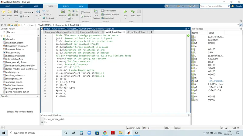
Consideration is as per followin-
Simulink Model is as below
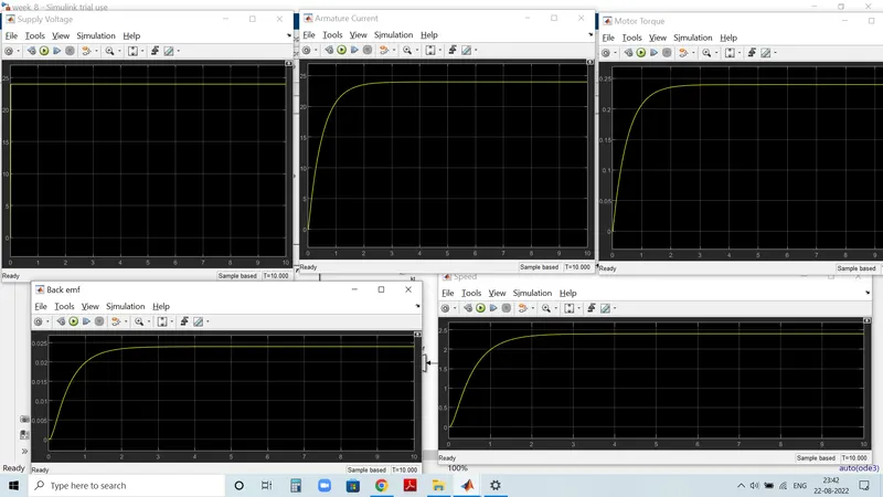
Graphs for the above Simulink mode is as shown below supply voltage is 24Volt and initial time is 0.01
Simulink model by using PID control is as per following
Plots for the above simulink model is as shown below
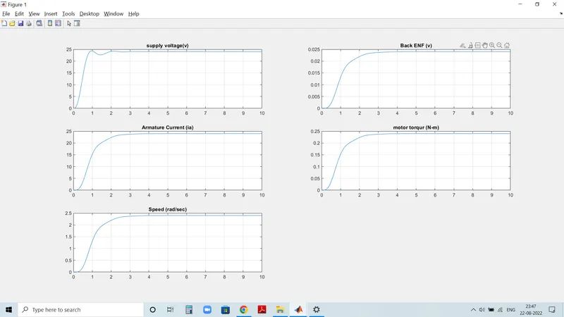
As shown in above supply voltage graph when we us PID control the settaling time less then 2sec & when we do not use PID controller then settaling time is 2sec or above 2sec.
We can achieve stability in the system by using PID controller
In above two cases,we maintain desired Speed For a Dc Motor.