Week-11 Challenge: Braking
Q.1) For a defined driving cycle, calculate the energy required for braking.
Explanation:
The Energy calculation required for Braking;
we have to identified what is happening to the vehicle under the Deceleration condition is similar to Acceleration condition. We say that so acceleration is increase in the speed increase and Declaration is a Reduction in speed so we require the Amount of calculate of Energy for Braking.
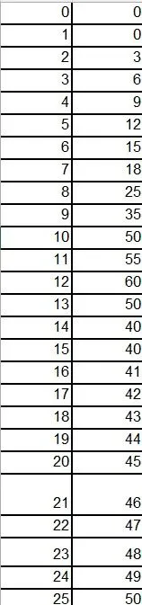
First of all, we have to defined the drive cycle in Excel sheet and a plot is made. Using the value from the braking regions of the vehicle are taken. The plot of the drive cycle is given below:
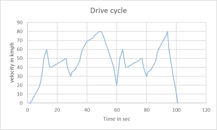
From the plot it is seen that, it consists of braking regions. The initial and final velocities are as given below.
| No:of Braking | Initial velocity (kmph) | Final velocity (kmph) |
| 1 | 60 | 40 |
| 2 | 50 | 30 |
| 3 | 80 | 20 |
| 4 | 60 | 40 |
| 5 | 50 | 30 |
| 6 | 80 | 0 |
.
Now from 100 to 0 how much Braking power is required for that calculate with formula
from the above values the deceleration values and total braking energy required to the vehicle are calculated using the excel calculator. The calculation is as given below: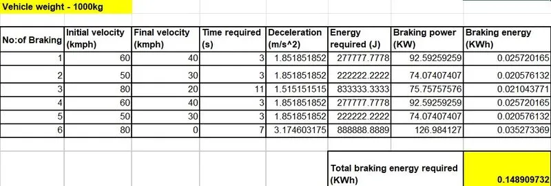
The total braking energy required = 0.14KWh.
Q.2) Why electric motor can’t develop braking torque at high speed similar to starting? How electric and mechanical brakes are coordinated?
Explanation:
This situation occurs only when the vehicle is at high speeds because the motor will be running at the constant power region. In the constant power region, the torque of the motor reduces and so the motor cannot develop the braking torque which is equal to the torque occurred during low speed at the constant torque region.
The torque vs speed plot of a control induction motor is given below:
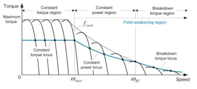
From the above characteristics curves of the motor remain high at low speed and reduces as the speed increases.
Therefore, electric motor cannot develop braking torque at high speed similar to starting.
Electrical brake and Machinal brake:
Electrical brake:
What is electrical braking?
The Electric Braking is stored energy in the rotating parts of an electric machine is converted into electrical energy and dissipated by the resistance in the form of heat or returned back to the supply. This braking method is called regenerative braking.
Electrical braking can be done by many methods such as,
- Unbalancing the input phases of current to the motor.
- Using transistor in H-bridge configuration to reverse the motor direction in order to reduces speed.
- Implementing the Regenerative braking system by using bi-directional power converters.
- Regenerative braking converts much of the energy to electrical energy, which may be stored for later use purpose.
Machinal brake:
Mechanical braking system:
It is the type of braking system in which the brake force applied on the brake pedal is carried to the final brake drum or disc rotor by the various mechanical linkages like cylindrical rods, fulcrums, springs etc. In order to stop the vehicle.
Co-ordination of Electrical and Mechanical braking in EV
There are two types brake control strategies used to co-ordinates the electrical brake and Mechanical brake they are;
1) Series control strategy
2) Parallel control strategy
The comparison of the control strategies is shown in the below:
In the figure it is that, according to the amount of brake of the pedal travel of the vehicle, the Mechanical and Regenerative brakes are applied.
- Series control strategy
If we want to STOP the vehicle then, at that time the brakes are applied with the brakes pedal, it travel in the front wheel friction brake, the rear wheel friction brakes and regenerative brakes are applied one after another. As the braking requirement increases the friction brakes are also increase.
For low speeds of the vehicle, regenerative braking is used but it may be limited according State of Charge of the Battery.
As the speed of the vehicle increases the rear wheel frictional brake will be applied, if the braking requirement is not satisfied yet then the front wheel frictional brake is used.
The Co-ordination of the series control braking can be done with preference to comfort of braking or Energy storage.
- Parallel control Strategy
When the Brakes are applied with the Peddle, according to the brake pedal, the rear wheel friction brakes and the regenerative brakes are simultaneously. The higher travel of the vehicle there is less Amount of Braking is required.
The braking Energy is Distrusted in the following manner:
Rear wheel friction > Front wheel friction > Regenerative Brake
- Electric driven intelligent brake (EDIB)
EBID is a Brake control strategy which is developed by NISSAN leaf.
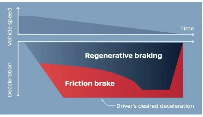
After stepping on the brake pedal, the system produces natural and adequate braking force that corresponds to the operation. In the case of an EV, the amount of energy regeneration also needs to be increased as much as possible. See Figure
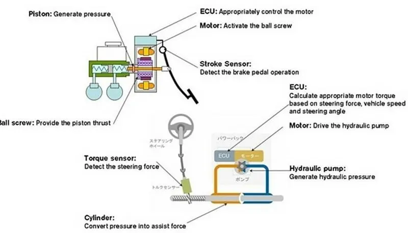
In the Electric Driven Intelligent Braking System, the braking force is provided with the help of a ECU controlled motor and ball screw arrangement. This means that no direct load on the engine while applying brakes. This means that a motor operated the brake for providing the braking energy. A more controlled and uniform braking force is applied since its ECU controlled, this helps to recover braking losses when a regenerative braking system is used. Hence it is parallel control strategy type braking.
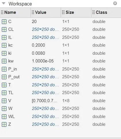
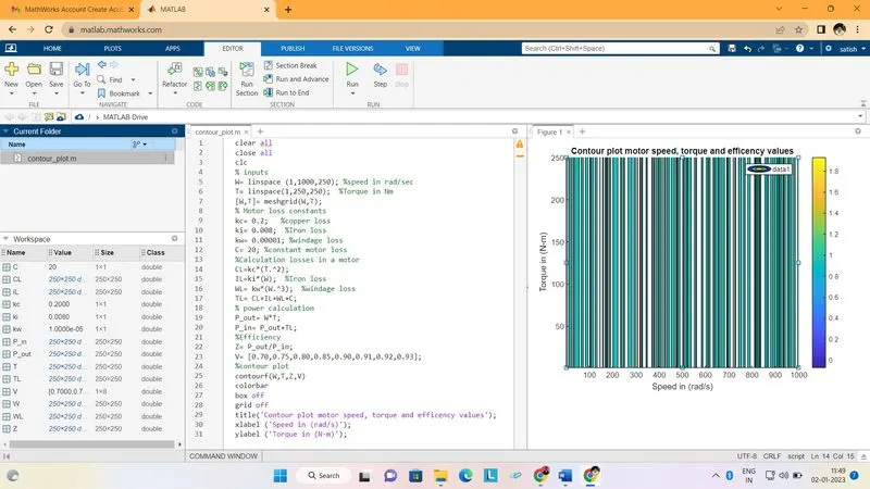
Q.3) Make a MATLAB program which plots contour of given motor speed, torque and efficiency values. Attach the code as a .m file attach a screenshot of all the plots.
Motor speed (W) = 1000 rad/s
Torque (T) = 250 m/s
Copper loss constant (kc) = 0.2
Iron loss constant (ki) = 0.008
Windage loss constant (kw) = 0.00001
Constant loss = 20
Formula used
Tl = CL + IL + WL + C
Where, TL = Total loss in motor
CL = Copper Loss in motor
IL = Iron loss in motor
WL = windage loss in motor
C = constant loss of the motor
CL = Kc*T^2
IL = Ki*w
WL = kw*w^3
Where, W = speed of the motor in rad/s
T = Torque of the motor in N-m
Output power = W*T
Input power = output power + TI
Efficiency = output power / input power
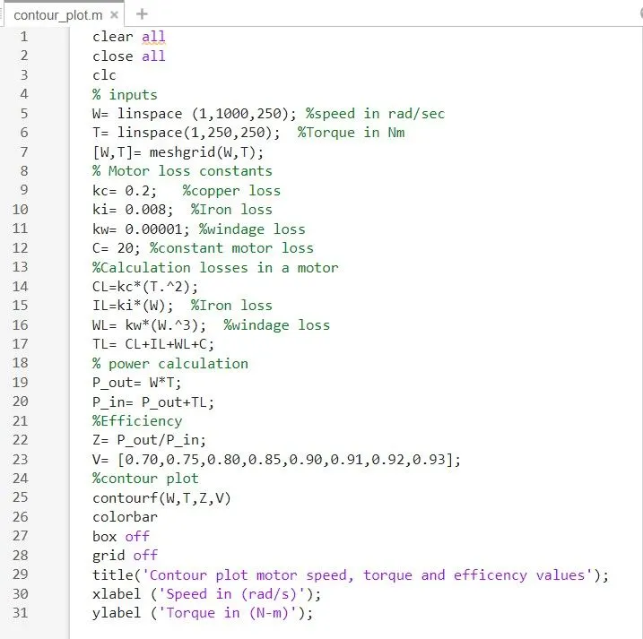
MATLAB code:
clear all
close all
clc
% inputs
W= linspace (1,1000,250); %speed in rad/sec
T= linspace(1,250,250); %Torque in Nm
[W,T]= meshgrid(W,T);
% Motor loss constants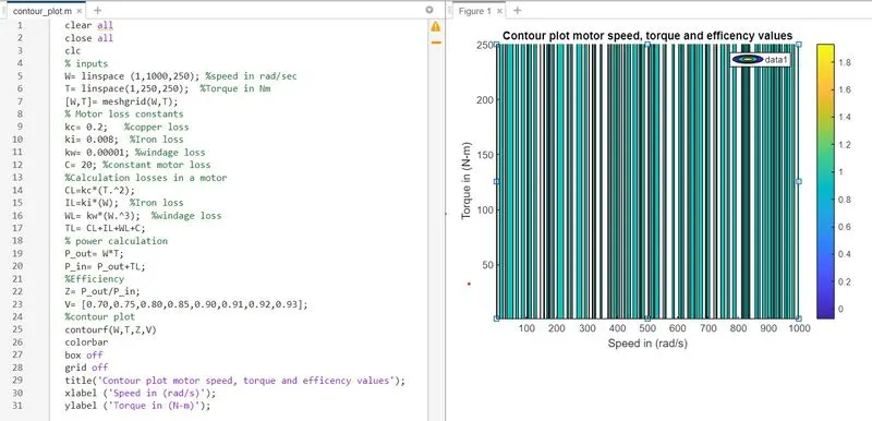
kc= 0.2; %copper loss
ki= 0.008; %Iron loss
kw= 0.00001; %windage loss
C= 20; %constant motor loss
%Calculation losses in a motor
CL=kc*(T.^2); % copper loss
IL=ki*(W); %Iron loss
WL= kw*(W.^3); %windage loss
TL= CL+IL+WL+C;
% power calculation
P_out= W*T;
P_in= P_out+TL;
%Efficiency
Z= P_out/P_in;
V= [0.70,0.75,0.80,0.85,0.90,0.91,0.92,0.93];
%contour plot
Contourf (W,T,Z,V)
colorbar
box off
grid off
title('Contour plot motor speed, torque and efficency values');
xlabel ('Speed in (rad/s)');
ylabel ('Torque in (N-m)');
Code Descreption:
- Then the motor constant values are assigned namely copper loss, ironloss, windage lossand constant motor loss.
- Then meshgrid is used to evaluate function of two variables and three-Dimensional mesh/surface plots.
- Output Power is calculated by multiplying speed and torque.
- Then all loss were calculated and the input power were also calculated.
- Then the effieiencies were calculated and Contour graph is plotted between speed and Torque and Effienciy.