Week -2
Q1). Make a Simulink model of Doorbell using solenoid block with the following details:
In the above arrangement, when the switch is closed the electromagnet receives electrical power from the battery and pulls the metal arm to hit the bell producing sound.
Create a situation where the switch is closed for 2 seconds and then released. Observe the physical movement of the plunger.
Assume remaining parameters.
Explaination:
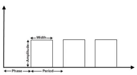
1) Pulse Generator: The Pulse Generator block generates square wave pulses at regular intervals. The block waveform parameters, Amplitude, Pulse Width, Period, and Phase delay, determine the shape of the output waveform. The block output can be generated in time-based or sample-based modes, determined by the Pulse type parameter.
2) Simulink-PS Converter: This converter converts the simulink signal to respective Physical signal.
3) Battery: This block is a storage device that provide the required voltage based on the parameter.
4) Switch: The Switch block models is a switch controlled by an external physical signal. If the external physical signal PS is greater than the value specified in the Threshold parameter, then the switch is closed, otherwise the switch is open.
5) Solver Configuration:The Solver Configuration block specifies the solver parameters that your model needs before you can begin simulation. Simscape block diagram requires exactly one Solver Configuration block to be connected to it.
6) Electrical Reference: This block represent an Electrical reference port. A model must contain at least one electrical reference port (electrical ground).
7) Solenoid: A solenoid is a device comprised of a coil of wire, the housing and a moveable plunger (armature). When an electrical current is introduced, a magnetic field forms around the coil which draws the plunger in. A solenoid converts electrical energy into mechanical work.
8) Ideal Force Sensor: The Ideal Force Sensor block represents a device that converts a variable passing through the sensor into a control signal proportional to the force.
9) Mechanical Translational Reference: It represent a Reference Point for to connect mechanical translational ports that are rigidly affixed to the frame (ground).
10) Scope: This is an output block which show the signal with respective to time on X-axis.
11) Display: The Display block shows the value of the input data
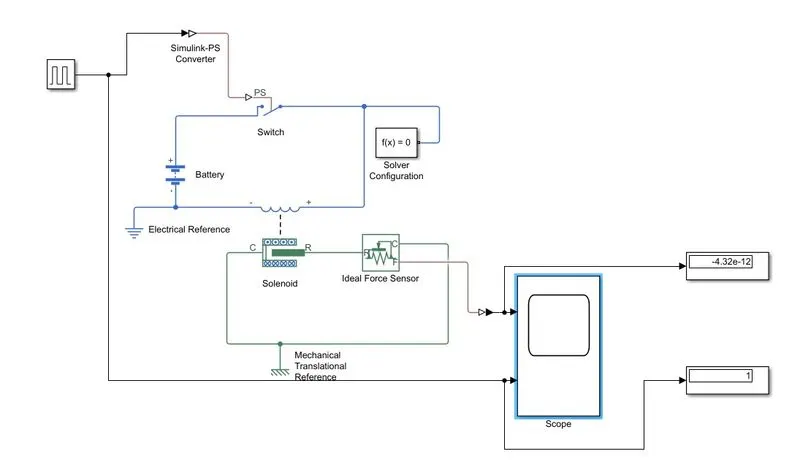
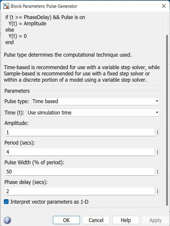
In the above circuit, we give in the Pulse Generator block parameter fed the parameter values Amplitude=1,Period=4 sec, Pulse width%=50 , Phase Delay= 2.
The Output of Pulse Genereator Block connected to PS-Switch after conversion by Simulink-PS converter. When the Switch is closed after getting signal from Simulink-PS Converter and Power Receive by Solenoid Block power from Battery it produce Electromagnet Force and the Plunger Will moves and that force feeding into the Ideal Force Sensor. The PS-Simulink Converter block convert the output of Ideal force Sensor it giving to Scope and Display we can observe Output and output in value also.
Scope of OUTPUT and INPUT Signal shown below:
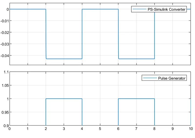
In the above signal waveform, we give in the Pulse Generator block parameter fed the parameter values Amplitude=1,Period=4 sec, Pulse width%=50 , Phase Delay= 2 sec.
Here, first 0 to 2 sec the Solenoid getting power from battery after that when Electromagnetic force produce 2 to 4 sec Plunger will move pulls of the metal arm to hit the bell producing sound and after that it released for 4 to 6 sec.
Q 2). Use a thermistor to sense the temperature of a heater & turn on or turn off the fan as per the below conditions:
Explanation:
INPUT:
Temperature source: 20 °C from 0 to 10 seconds,
27 °C from 10 to 30 seconds,
23 °C from 30 to 50 seconds
OUTPUT:
Fan conditions: ON if the temperature above 25 °C,
OFF otherwise.
Explaination:- Here, we do not measure Celsius with respect to time directly. Celsius is not give absolute zero value.
Temperature is a physical quantity that expresses the hotness of matter or radiation.
Why do we need to convert Celsius to Kelvin?
Celsius or Fahrenheit are not directly related to kinetic energy or volume because these scales do not begin at zero. Researchers use the Kelvin scale because it is an absolute scale of temperature which is directly related to kinetic energy and volume.
Many scientific measurements use the Kelvin temperature scale (unit symbol: K). It is an absolute scale. Its numerical zero point, 0 K, is at the absolute zero defined as 0 K, is exactly equal to −273.15 °C of temperature.
Given Data:
20 °C from 0 to 10 seconds,
27 °C from 10 to 30 seconds,
23 °C from 30 to 50 seconds.
Conversion from Celsius to Kelvin:
a) 0 °C + 273.15= 273.15 k
b) 20 °C + 273.15= 293.15 k
c) 27 °C + 273.15= 300.15 k
d) 23 °C + 273.15= 296.15 k
e) 25 °C + 273.15= 298.15 k
In the given condition is that ON if the temperature above 25 °C (298.15), that is 27 °C = 300.15 k.
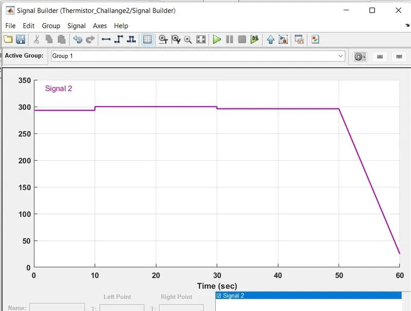
1) Signal Builder: This block is used to generate the signal according to the given condition.
2) Simulink-PS Converter: This converter converts the simulink signal to respective Physical signal.
3) Controlled Temperature Source: This block represents an ideal energy source in a thermal network.The temperature difference is set by the physical signal port S. A positive temperature difference causes the temperature at port B to be greater than the temperature at port A.
4) Thermal Reference: This block represents a reference point in a thermal network where the temperature is equal to absolute zero.
5) Battery: This block is the battery as a series internal resistance and a constant voltage source.
6) Thermistor: The Thermistor block represents the relation between Resistance and Temperature. Thermistor is a Temperature sensor. NTC thermistors have less resistance at higher temperatures.
7) Resistor: The Resistor block which provide oppising the nature current in the circuit .
8) Constant: Use this block to provide a constant signal input.
9) Electrical Reference: This block represent an Electrical reference port. A model must contain at least one electrical reference port (electrical ground).
10) Voltage sensor: The Voltage Sensor block converts voltage measured between two points of an electrical circuit into a physical signal proportional to the voltage.
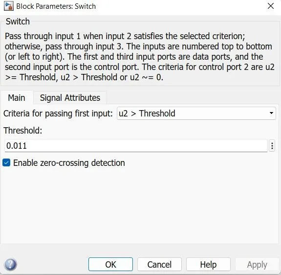
11) Switch: The Switch block passes through the first input or the third input signal based on the value of the second input. The first and third inputs are data input. The second input is a control input.
The criteria for control port 2 are u2 >= Threshold, u2 > Threshold or u2 ~= 0.
12) Solver Configuration: The Solver Configuration block specifies the solver parameters that your model needs before you can begin simulation. Simscape block diagram requires exactly one Solver Configuration block to be connected to it.
13) PS-Simulink Converter: This converter converts the Physical signal to respective simulink signal.
14) Scope: This is an output block which show the signal with respective to time on X-axis.
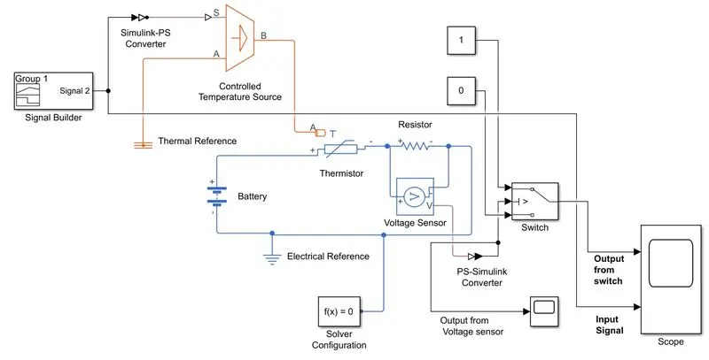
In the above circuit, an NTC Thermistor get from the Library of Simulink: Simscape/ Foundation Labrary/ Electrical/ Electrical Elements.
The Thermistor has a two Electrical port which are + and - that are connected to Battery, along with two terminal we had a H port also which provide the resistance temperature. This port A is connected to Controlled Temperature source block which provide the required temperature according to the signal provided to its Port A which is inlet source and Port B is the output port of the Thermistor. Here our Resistor act as Load (FAN) and the Voltage sensor from simscape is parallel conected with Resistor to measure the voltage across the Thermistor and the Voltage sensor give the value in physical signal and it is convert in Simulink signal and the Output of the PS-Simulink Converter is connected Scope to observe and Thershold value of the Switch Block.
Voltage Sensor Output:
Use the + and - ports to connect the sensor in parallel with the Resistor block (or several blocks) where you want to measure the voltage. Port V outputs the measurement result as a physical signal
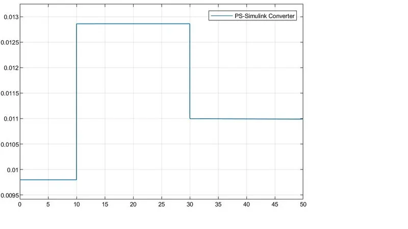
Thershold value: (It means set a limit value on a scale) Here we have three inputs of switch by using two constant block in giving at one input=1 and other input 3=0 and input 2= Threshold value i.e. 0.011
Output from the Switch upper signal and Input from signal Builder Below signal:
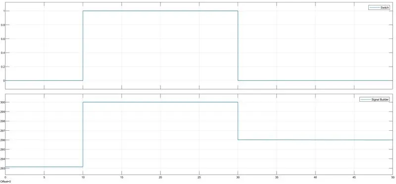
In the given condition is that ON if the temperature above 25 °C (298.15), that is 27 °C = 300.15 k, FAN should goes ON for 10 to 30 Sec.