Week-11 Challenge: Braking
Q.1 For a defined drive cycle calculate the energy requirement for braking
let assume the mass of vehicle is M=500 kg.
drive cycle defined is
| Time t(sec) | speed (m/s) |
| 0 | 0 |
| 1 | 10 |
| 2 | 20 |
| 3 | 30 |
| 4 | 40 |
| 5 | 60 |
| 6 | 40 |
| 7 | 80 |
| 8 | 100 |
| 9 | 20 |
| 10 | 0 |
we have to calculate the value of energy required for braking
vehicle speed is braking in the interval of Time which is at t=5sec
initial speed =60 m/s and final speed =40 m/s
Braking Energy E1=1/2*M*(Final-initial speed)^2=0.5*500*400 =100000 J=100 KJ
Braking energy at time t=8 sec
E2=1/2*500*(20-100)^2=1600000=1600KJ
Braking energy at time time t=9
E3=1/2*500*(0-20)^2=100000=100 KJ
so total energy in braking for a defined drive cycle is
E=E1+E2+E3=100+1600+100=1800 KJ
Energy in braking =1800 KJ
Q.2 ANSWER
Electric motor can't develop braking torque at high speed" - Reason:
Now Speed torque characteristics of motor is shown below,
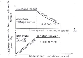
Here it is clearly shown in the first graph that till the motor reaches the critical speed it has constant torque and once it reaches the critical speed, the curve is having a down slope which is a constant power region. And this graph denotes the accelerating operation of the motor. For the deceleration or braking operation of the motor, this graph is mirrored down which will be having the speed (+ve) and torque (-ve).
For example,
we can say that an EV can achieve 0-100 kmph in 10sec. Acceleration operation goes this way, with low speed and high torque Constant torque region is achieved which has accelerating power and by reaching the critical speed it shifts to constant power region and thus it easy for an EV to reach 0-100 kmph.
As said the breaking operation graph will be th mirrored image of above plot. So we cannot say that the motor producing 7Nm torque for acceleration can also produce -7Nm for breaking. Because we are operating in the field weakening region, and operating above the base speed. Thus Peak Acceleration torque is greater than the Peak Deceleraion torque. Thus for acceleration it has high torque with low speed and for deceleration it has low torque for high speed.
Electric and mechanical brakes are coordination:
There are two brake control strategies namely, SERIES & PARALLEL.
SERIES:
Brakes will be applied one after the another so which they are connected in series. Either one brake stragety at a time either Regenerative braking or Mechanical braking at a time.
PARALLEL:
In case of parallel both the brakes are applied simultaneously, Both at a time.
ELECTRIC DRIVEN INTELLIGENT BRAKE:
And Nissan has developed a practical brake strategy called ELECTRIC DRIVEN INTELLIGENT BRAKE (EDIB)developed by Nissan leaf
Technology Functionality:
After stepping on the brake pedal, the system produces natural and adequate braking force that corresponds to the operation. The amount of energy regeneration also needs to be increased as much as possible. EDIB (Electric Driven Intelligent Brake) controls the regenerative brake and friction brake to support both of these requirements. Further, it also controls the reactive force from the pedal in order to unify the feeling when stepping down on the pedal and the sense of deceleration.
Conclusion
1.Braking torque is low as compared to accelerating torque because in the case of accelerating torque it is used to change at a very high speed at the time of starting so as per in constant torque region value is high.
2. Battery discharging rate is higher as compared to charging rate due to chemical composition of the battery.
3.Power converter design becomes complex in nature in reverse direction of applying torque in braking .
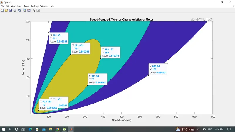
Q.3 Contour plotting
matlab script
Conclusion
1.For the given values the 90% effieciency was achieved.for a iven value of speed and torque third term is basically effieciency .