Week-11 Challenge: Braking
Quetion 1:
Aim: To calculate the energy required for braking, for a defined driving cycle.
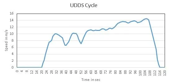
The driving cycle taken into consideration is the UDDS cycle which stands for Urban Dynamometer Driving Schedule. Although the data is taken for a total driving time for 1370s, for simplicity sake on 120s of driving time is considered. The speed which is in miles per hour has been converted to meters per second.
The drive cycle is given below.
the quation for braking power of an vehicle is
`"Breaking Power"=1/2xx((mxxV^2))/((txx1000))`
where, m is Total mass of the vehicle
V is vehicle speed in m/s
and also `V=v_i-v_f`
where `v_i` is initial speed of the vehicle
`v_f` is final speed of the vehicle
t is deceleration time
by implementing all these values in excel sheet i created a table to calculate the total breaking energy required by the vehicle
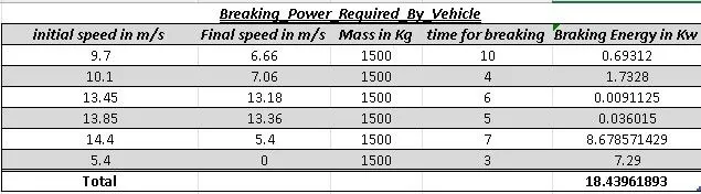
from the table we will get the total braking power required by the vehicle
let us calculate the total braking energy required by the vehicle
`E_b=P_b/3600`
`=>18.44/3600`
`E_b=0.00513kwh`
the total braking energy required by the vehicle `E_b " is " 0.00513kwh`
Question 2:
Aim: To Explain electric motor can’t develop braking torque at high speed similar to starting and How electric and mechanical brakes are coordinated
Let us consider the torque speed characteristics.
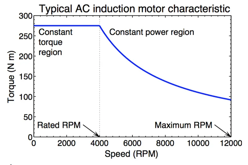
From this curve we have two region, constant torque and constant power region. At the start the motor achieves peak torque till it reaches a certain motor speed range from where it will rapidly drop. The reason due to the drop in torque is due to the motor shaft reaching critical speed and the area where the peak torque is constant is known as the constant torque region of the motor. The region where the torque decreases is known as the constant power region as the power generated by the motor will be at it's peak.
Since the torque produced at the constant power region is very low, it is not possible to develop enough braking torque in this region. The braking torque produced increases as the speed decreases.
How are electric brakes and mechanical brakes co-ordinated?
In electric vehicles, two types of braking systems are used electric brake system and mechanical brake system.
Electric Braking System: In electrical braking, the winding of the motor is used to produce a braking torque. A braking torque is developed during the braking operation. This braking torque opposes the motion of the rotating member or shaft. This is achieved by suitably changing the electrical connections of the motor. The motor operates on a speed–torque characteristic, depending upon the method of braking employed.
Mechanical Braking System: In mechanical braking, the frictional force between the rotating parts and the brake drums produces the required braking. To achieve this, mechanical equipment, such as brake linings and brake drums, are required. Whether electrical or mechanical, the braking of the drive should stop the motor at the specified point of time and position.
The electric braking system used in EVs and HEVs is regenerative braking. This method uses the motor as a generator during braking, developing a retarding torque, which acts on the running motor and halts it. The kinetic energy and potential energy, minus the losses of the motor are returned to the mains and the motor runs at a constant speed. Thus, regenerative braking eliminates the tendency of the load to accelerate the motor.
Mechanical braking systems used can be either disc or drum brake system. Where in case of a disc brake system friction pads rub against a disc when the brake pedal is applied and the kinetic energy is converted to heat and slows the vehicle down. In a drum brake system a set of brake shoes which are the friction materials press against a drum.
Since the braking torque is very less at high speeds, mechanical brakes are applied to slow down the vehicle. As the motor reaches the constant torque region the regenerative braking system takes effect where the motor acts as a generator and the negative torque produced charges the battery pack.
Question 3:
Aim: To Make a MATLAB program which plots contour of given motor speed, torque and efficiency values.
The speed and torue charecteristics are achieved by considering the certain values but, efficiency calculation includes many values like
- speed
- torque
- input power
- output power
- iron or core losses
- copper losses
- windage losses
to clculate efficiency the above values can be considered
let us know the formulas for each of them
copper losses or `I^2R`losses
`C_l=k_cxxtau^2`
where `k_c`is copper loss constant
`tau`is torque
Iron Losses
`I_l=k_ixxomega`
where
`k_i`is iron loss constant
`omega`is speed of the motor
Windage losses
`W_l=k_wxxomega^3`
where `k_w`is windage loss constant
Constant Losses
c
the total losses in the motor is given by
`"Total"_l = C_l+I_l+W_l+c`
now to calculate the output power
`P_("out")=tauxxomega`
now to calculate input power
`P_("in")=P_("out") +"Total"_("losses")`
Now to calculate the eficiency of the Motor
`eta = P_("out") /P_("in")`
lets create a program that the speed values are taken from 0 to 1000 and the torque values are taken from 0 to 250 using linspace
the losses constants are taken according to the typical induction motor
the programme is
w = linspace(1,1000);%sspeed of the motor
T = linspace(1,250);%Torque of the motor
kc = 0.2;%copper loss constant
ki = 0.008;%Iron loass constant
kw = 0.00001;%Windage loss constant
c = 20;%Constant loss
[X,Y] = meshgrid(w,T);%Due to array the mesh grid extracts from the array
P_o = (X.*Y);%output power
C_l = (Y.^2)*kc;%Copper loss
I_l = X*ki;%Iron loss
w_l = (X.^3)*kw;%Windage Loss
P_i = P_o + C_l + I_l + w_l + c;%input power
n = P_o./P_i;%efficiency
V = [0.7,0.8,0.85,0.9,0.91,0.92,0.925,0.93];%contour mapping
box off
grid off
contour(X,Y,n,V);
xlabel('speed in rad/sec');
ylabel('Torque in N-m');
legend('0.7,0.8,0.85,0.9,0.91,0.92,0.925,0.93');
hold on;
the above programme is an speed torque efficiency charecteristics plotting program
in which the torque and speed value are taken as arrays by linspace command
with help of meshgrid we can extract the values at points
the program is designed to create a contour for speed torque and efficiency at particular efficency points
which are
0.7,0.8,0.85,0.9,0.91,0.92,0.925,0.93
we can observe the particularity in the below contour
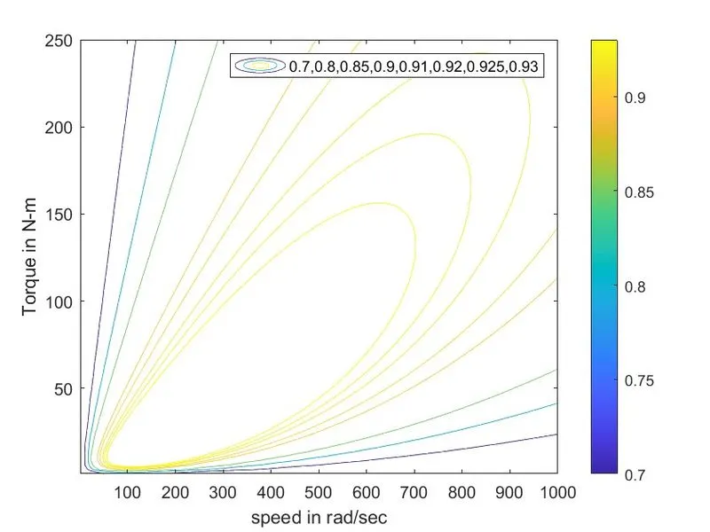
from the contour we can observe that the speed and torque varies as the efficiency increases
the side strip mentions the efficiency as bright blue mentions 70% efficienct and bright yellow represents 90% efficiency
thus the speed, Torque and efficiency charecteristics are plotted
Conclusion:
- The Braking Energy Required by an Vehicle is Calculated for a Drive Cycle Using Excel Spreed sheet.
- The coordination between electrical and mechanical braking is expalined as well as why electrical braking exhibits less power during high speeds.
- The speed, Torque and Efficiency charecteristics Contiur is plotted by MATLAB program.