Week-6 Challenge: EV Drivetrain
Question 1:
Aim: To Explain the types of power converter circuits are employed in electric and hybrid electric vehicles.
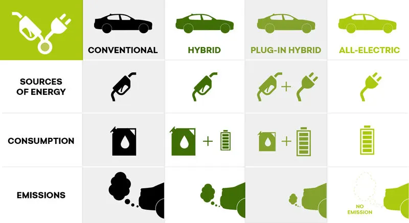
We know generally there are three types of Electrical vehicles.
- Hybrid Electric vehicle
- Plugin Hybrid Electric vehicle
- Battery Electric vehicle
Hybrid Electric vehicle:
- Hybrid Electric Vehicles, or HEVs, have both a gas-powered engine and an electric motor to drive the car.
- All energy for the battery is gained through regenerative braking, which recoups otherwise lost energy in braking to assist the gasoline engine during acceleration.
- In a traditional ICE vehicle, this braking energy is normally lost as heat in the brake pads and rotors
- Regular hybrids cannot plug into the grid to recharge and cannot charge with electric chargers
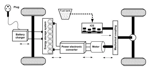
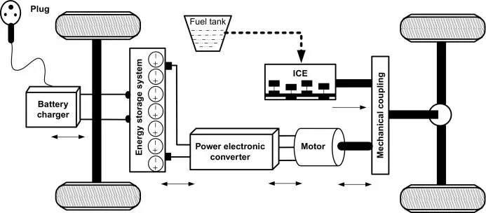
Plug-in Hybrid Electric vehicle:
- Plug-in Hybrid Electric Vehicles, or PHEVs, have both an engine and electric motor to drive the car.
- Like regular hybrids, they can recharge their battery through regenerative braking.
- They differ from regular hybrids by having a much larger battery and being able to plug into the grid to recharge.
- While regular hybrids can (at low speed) travel 1-2 miles before the gasoline engine turns on, PHEVs can go anywhere from 10-40 miles before their gas engines aid.
- Once the all-electric range is depleted, PHEVs act as regular hybrids, and can travel several hundred miles on a tank of gasoline.
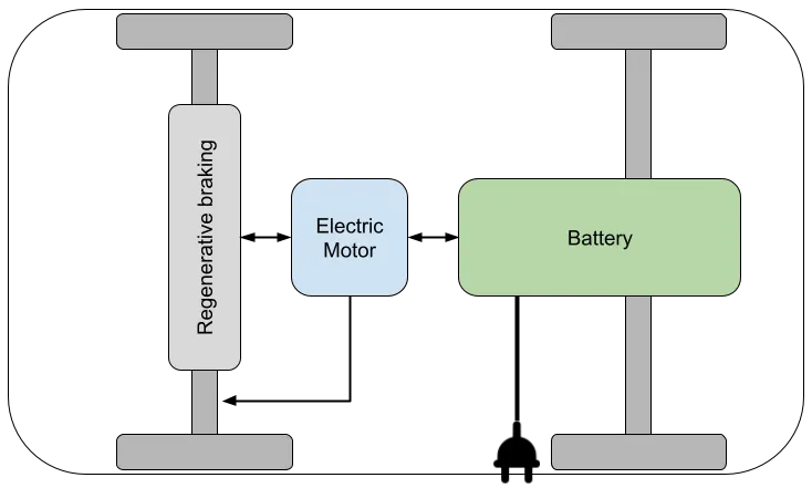
Battery Electric vehicle:
- Battery Electric Vehicles, also called BEVs and more frequently called EVs, are fully electric vehicles with rechargeable batteries and no gasoline engine.
- BEVs are zero emissions vehicles, as they do not generate any harmful tailpipe emissions or air pollution hazards caused by traditional gasoline-powered vehicles.
- All energy to run the vehicle comes from the battery pack which is recharged from the grid.
But in all these types of vehicles, we use basically 3 types of power converters.
They are
- AC-DC converter
- DC-DC converter
- DC-AC converte
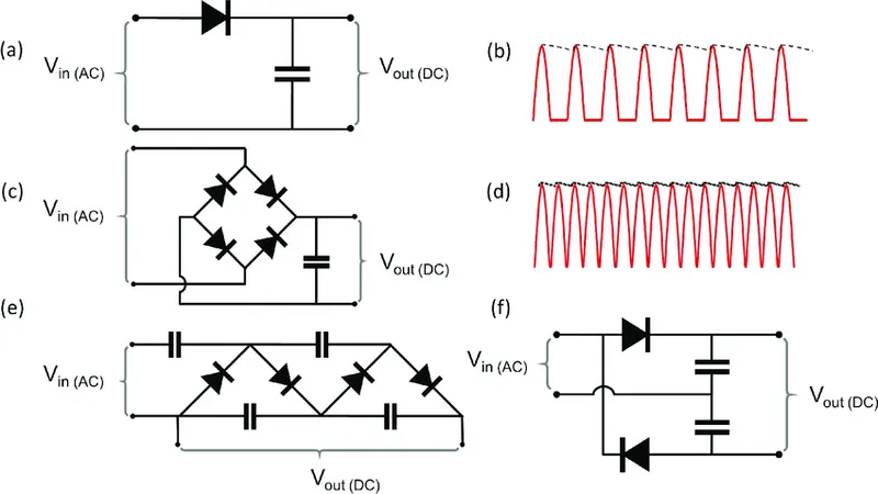
AC-DC Converter(Rectifier):
- AC-DC converter (Onboard charger) is used for charging the vehicle.
- As battery stores energy in the form of DC, so AC-DC power converter is required.
- They are generally used in PHEV and PEV type vehicles.
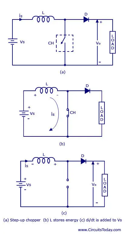
DC-DC Converter (Chopper):
- We know lights, indicators and other signal generators requires only low voltage (12V or 24 V)
- So, the battery energy (DC type high range) will convert into Low voltage DC by DC to DC converter (Chopper).
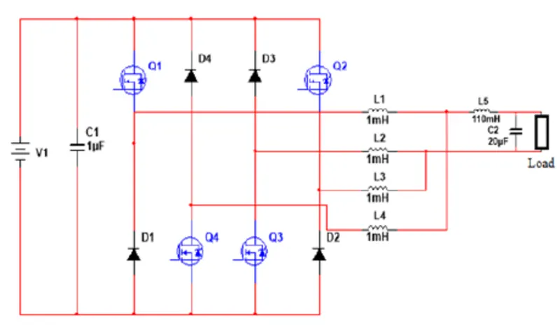
DC-AC Converter (Inverter):
- DC-AC converter is used to convert the battery energy (DC type) to AC to supply the motor (AC motor used).
- Therefore, the converted energy (AC) is used for motor operation.
Question 2:
Aim: To calculate the EV steady state speed if duty cycle is 70%
Given that
Rated Armature voltage `V_A` = 72 V
Rated armature current `I_A` = 400 A
`R_A`= 0.5Ω
`Kphi`= 0.7 Volt second
Chopper Switching frequency= 400 Hz
given vehicle torque
`tau_v=24.7+(0.0051)omega^2`
we know the torque of the motor
`tau_m = (K phi)/(R_A) [V_A-Kphi*omega]`
we are considering the condition to extaract the value of `omega`where
`tau_v=tau_m`
These values are programmed and calculated in MATLAB to find the steady state speed of the vehicle
%motor and controller parameters
Va = 72;%rated armature voltage
ia = 400;%rated armature current
Ra = 0.5;%armature resistance
Kphy = 0.7;%flux constant volt-sec
Fc = 400;%chopper frequency
delta = 70/100;%duty cycle
Vs = Va*delta;%voltage
w = 0:0.01:50;%angular velocity rad/sec
Tv = 24.7+(0.0051.*w.^2);%vehicle torque
Tm = ((Kphy*Vs)/Ra)-(((Kphy)^2/Ra)*w);%motor torque
plot(w,Tv);
grid;
title('steady state speed of Ev');
xlabel('w(rad/s)');
ylabel('T(N-m)');
hold;
plot(w,Tm);
we will get the output as
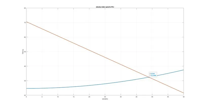
by observing the plot we can get the angular velocity as 38.93rad/sec
steady state speed of EV is `omega`=38.93 rad/sec or 371.76 RPM
Question 3:
Aim: To simulate the mathematical model of DC motor `omega = V/(Kphi) - (R_A)/(Kphi)^2 *tau`
considering the above values and using the same workspace except `tau`
as `tau_m`value is an 1x5001 double MATLAB takes long duration to simulate
instead considering Ramp as it is an linearly increasing function acts as an torque
by above values simulink model is built
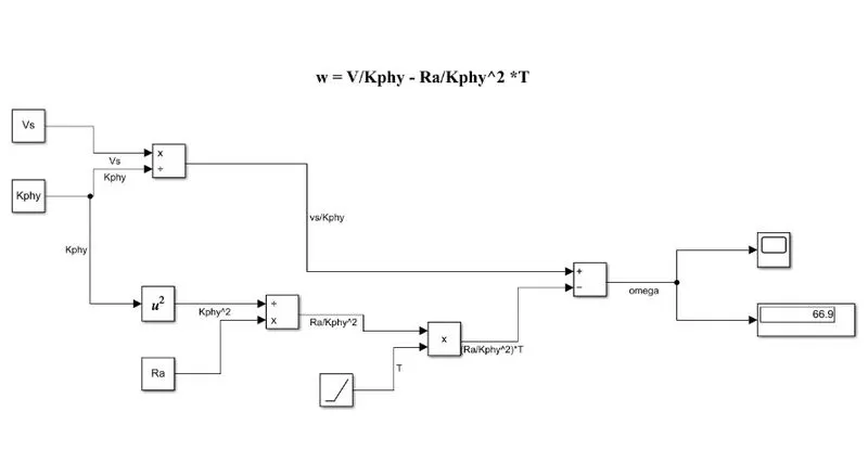
the model settings are fixed to fixed step ode45 runguecutta method
the output is
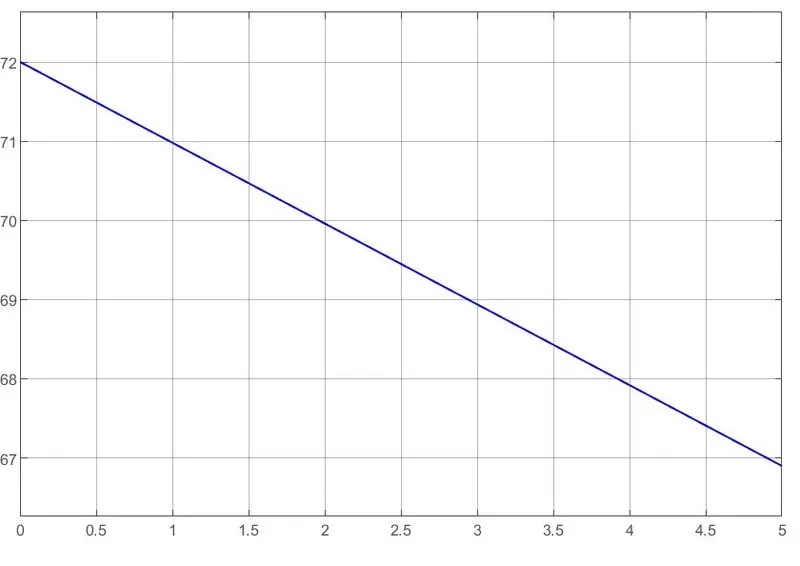
the mathematical model of an DC motor speed is built and simulated.
Question 4:
Aim: To explain brief about author’s perspective Induction Versus DC brushless motors by Wally Rippel, Tesla
The author shared many things in which we need to discuss the topic induction motor vs DC brushless motor
- Both DC brushless and induction drives use motors having similar stators.
- Both drives use 3-phase modulating inverters.
- The only differences are the rotors and the inverter controls. And with digital controllers, the only control differences are with control code.
- DC brushless drives require an absolute position sensor, while induction drives require only a speed sensor; these differences are relatively small.
- One of the main differences is that much less rotor heat is generated with the DC brushless drive.
- Rotor cooling is easier and peak point efficiency is generally higher for this drive.
- The DC brushless drive can also operate at unity power factor, whereas the best power factor for the induction drive is about 85 percent.
- This means that the peak point energy efficiency for a DC brushless drive will typically be a few percentage points higher than for an induction drive.
- In an ideal brushless drive, the strength of the magnetic field produced by the permanent magnets would be adjustable. When maximum torque is required, especially at low speeds, the magnetic field strength (B) should be maximum – so that inverter and motor currents are maintained at their lowest possible values.
- This minimizes the I² R (current² resistance) losses and thereby optimizes efficiency. Likewise, when torque levels are low, the B field should be reduced such that eddy and hysteresis losses due to B are also reduced.
- Ideally, B should be adjusted such that the sum of the eddy, hysteresis, and I² losses is minimized. Unfortunately, there is no easy way of changing B with permanent magnets.
- induction machines have no magnets and B fields are “adjustable,” since B is proportionate to V/f (voltage to frequency). This means that at light loads the inverter can reduce voltage such that magnetic losses are reduced, and efficiency is maximized.
- Thus, the induction machine when operated with a smart inverter has an advantage over a DC brushless machine – magnetic and conduction losses can be traded such that efficiency is optimized.
- This advantage becomes increasingly important as performance is increased.
- With DC brushless, as machine size grows, the magnetic losses increase proportionately and part load efficiency drops.
- With induction, as machine size grows, losses do not necessarily grow. Thus, induction drives may be the favoured approach where high-performance is desired; peak efficiency will be a little less than with DC brushless, but average efficiency may be better.
- Permanent magnets are also very costlier as China is the only largest supplier of permanent magnets.
- Use of permanent magnets results in various forces play when anything gets close to them.
- Induction machines are more difficult to control. The control laws are more complex and difficult to understand. Achieving stability over the entire torque-speed range and over temperature is more difficult with induction than with DC brushless.
- By studying the blog, I understood that Although the DC brushless motor have an few more advantages over induction motor the author suggests the induction motor only due to its operation and low manufacturing cost and better performance.
- But so many alternatives are invented to avoid the flaws of DC brushless except the permanent magnets as they are rare.
- Synchronous reluctance motor (SRM) is developed to overcome the problem of rare earth magnets and also efficiency, even though it has its own flaws they are overcome in future by better technology.
Conclusion:
- Different types of Power converters that are employed in pure electric and hybrid electric vehicles are explained.
- The EV steady state speed at duty ratio 70% is calculated using the MATLAB
- The mathematical model of an DC motor speed is simulated using SIMULINK
- Induction motor versus DC brushless motor by wally rippel, TESLA blog is studied and explained briefly in my view.