Week-11 Challenge: Braking
Aim:
Braking
Objective:
Calculating the energy needed for braking of UDDS Drive Cycle-
Braking: Braking could be a condition to cut down or stops a moving vehicle pro re nata. There area unit many techniques to use brakes, which might be mechanical or electrical. the foremost usually used technique is by applying friction. It consumes energy .The consumed mechanical energy is derived as following equation-
Braking Energy = (1/2)*m*v^2
Where, Braking Energy is that the mechanical energy in unit of Joule.
m= Total Mass of the Vehicle (Vehicle Mass + Pay Load) in unit of kilogram.
v= (Initial Velocity-final Velocity) in unit m/s.
For Example if Initial speed of a vehicle is 20m/s and final speed is 10m/s. The mass of the vehicle is 500kg. Then the specified mechanical energy for Braking is (1/2)*500*(20-10)^2 = 25000 J =25KJ
Here for a Drive cycle the specified braking energy is calculated for every second of your time to cut down or stop the vehicle- Braking Energy Calculation for UDDS Driving Cycle
Q2. Why motor can’t develop braking force at high speed like starting? however electrical and mechanical brakes area unit coordinated?
DC motor force vs Speed Characteristic
Here for each just in case of AC or DC there's no force at most speed, bit by bit the force decreases at high speed because the speed tends to be most speed. this example doesn't occur at the start of acceleration as a result of most of the force is employed to extend the mechanical energy of the load (and motor). however once the speed is already high and no additional load is applied it's impracticable to extend the force in addition on develop braking force. The braking operation happens within the motion that is been distributed as per proportion within the Brake Energy and also the regenerative braking.
There area unit 2 sorts of braking:
(i)Mechanical Braking: Mechanical brakes all act by generating resistance forces as 2 surfaces rub against one another. The stopping power or capability of a brake depends mostly on the area of resistance surfaces in addition as on the exploit force applied. Mechanical brakes area unit assemblies consisting of mechanical parts for the retardation or stopping of shafts in instrumentality drives. They use levers or linkages to transmit force from one purpose to a different. Braking slows or stops the movement of the coupled shafts. There area unit many sorts of mechanical brakes.
1) Band brakes: These area unit the only brake configuration, have a metal band lined with heat and wear resistant friction material.
2) Drum brakes: These area unit usually used on automobile rear wheels, work once shoes press against a spinning surface known as a drum.
3) Disc brakes: These area unit made of constraint, a calliper, and a rotor. throughout operation, the constraint area unit squeezed against the rotor.
(ii) electricalal Braking: Electric brakes area unit devices that use associate electrical current or magnetic causative force to slow or stop the motion of a rotating element. they're employed in industrial and transport braking applications that need quick response times and precise tension management. The magnet within the backing plate has two conductor wires that faucet directly into the wiring. once electricity is on, it magnetizes the brake magnet. The magnet is interested in the drum face. once it contacts this space, the friction causes it to rotate, that moves the causative arm, and pushes the shoes out against the drum. Those shoe have a special brake pad material on them that resists the warmth caused by that friction. once the shoes press against the within of the drum, they stop the hub, and consequently the wheel that is touching the bottom.
A very stunning electrical braking theme known as Regenerative Braking is currently being used for electrical braking. Here throughout the braking action, the motor is operated as generator. As we all know that in generating action, a counter force is created. therefore this counter force opposes the motion of motor and motor involves halt. Moreover, the brake energy is born-again to power which might be fed back to the supply victimization power converters.
Electric and Mechanical brake coordination:
There area unit primarily two {ways|ways that|ways in that} by which the electrical Vehicles may well be braked:
Series- Regenerative braking and mechanical braking each area unit applied one when another.
Parallel- Regenerative braking and mechanical braking each area unit applied at the same time.
When treadle is ironed the hydraulic fluid reaches the brake pistons and created the braking pressure on the wheels and also the same mechanical energy is been utilized by the Regenerative Braking for generating a lot of power victimization the Bi-directional motor that operates as a generator whereas braking.
3) Make a MATLAB program which plots contour of given motor speed, torque and efficiency values. Attach the code as a .m file attach a screenshot of all the plots.
clear all
close all
clc
% Speed Array
omega = linspace(0, 300, 100);
% Torque Array
T = linspace(0, 2000, 100);
% Meshgrid
[X,Y] = meshgrid(T, omega);

% Loss Coefficients
cu = 0.17;               % Copper coefficient
fe = 0.006;              % Iron coefficient
win = 0.000015;          % Windage coefficient

% Losses
cu_loss = cu*(Y.^2);     % Copper Losses
fe_loss = fe*(X.^2);     % Iron Losses
win_loss = win*(X.^3);   % Windage Losses
cond_loss = 18;          % Conduction Losses

% Output Power
P_out = (X.*Y);
% Input Power
P_in = P_out + (cu_loss) + (fe_loss) + (win_loss) + (cond_loss);
% Efficiency
n = ((P_out)./(P_in));

% Efficiency values for contour
W = linspace(0.75, 0.95, 10);
% Contour Plot
contour(X,Y,n,W)
xlabel('Angular Speed, rad/s')
ylabel('Torque, Nm')
title('Speed, Torque and Efficiency characteristics of Motor')
In this MATLAB script, we tend to produce arrays for the speed and also the force of the motor exploitation the ‘linspace’ command. For the speed, take into account a variety of values from zero to 2000 radians per second whereas for the force, take into account a variety of values from zero to 300Nm.These arrays square measure then wont to produce 2nd grid coordinates exploitation the ‘meshgrid’ command. These coordinates can facilitate within the creation of the contour plot. so as to seek out the potency of the motor, we'd like to contemplate the varied losses that occur within the motor’s operation. These are:
Copper losses
Iron losses
Windage losses
Conduction losses
These numerous losses square measure addicted to the speed and also the force of the motor. They every even have a characteristic constant of quotient that square measure all assumed for the subsequent calculations and portrayed as 'K'. In every calculation, the speed and also the force square measure portrayed severally as: ω and T.
Copper losses = KCu⋅ω2
Iron losses =KFe⋅T2
Windage losses =Kw⋅T3
The values of coefficients square measure taken as general values. physical phenomenon losses square measure assumed to be eighteen Joules.
Finally we tend to plot the contour with the 'contour' command. additionally, AN array for the potency values we would like to plot for is made known as 'W' ANd is appointed for values starting from an potency level of zero.75 to 0.95. This array is employed within the creation of the contour. Axis labels and a title is additionally created for higher readability.
Output:
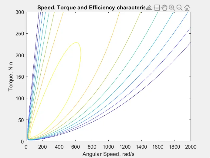
From this contour plot, we will see that the very best level of potency arises within the innermost contour plot and this potency decreases because the contours increase in size from the innermost contour.