Week-11 Challenge: Braking
- For a defined driving cycle, calculate the energy required for braking.
Answer: -
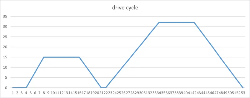
consider drive cycle as below where we are applying brake for 2 times at diffrent speed and for different time.
Braking power = 0.5*m*v^2
let mass of the vehicle is 1000 Kg
14.99 mps to 0 in 5 sec hence power required is 11.24 KW (in 5 sec)
Hence energy required is 11.24/3600 =3.12*e-3KWh in 5 sec.
31.99 mps to 0 in 11 sec hence power required is 23.27 KW (in 11 sec)
Hence energy required is 23.27/3600 =6.46*e-3KWh in 11 sec.
Total power required for the braking is 34.51 KW.
Total energy required for the braking purpose is 9.58*e-3 KWh
excel sheet for calculation is attached below.
https://docs.google.com/spreadsheets/d/1al_8f21eLGh1Ucu8RMqJ7iBS6VmrFnXn/edit?usp=sharing&ouid=115966497364200250112&rtpof=true&sd=true
--------------------------------------------------------------------------------------------------------------------------------------------------------------
2.Why electric motor can’t develop braking torque at high speed similar to starting? How electric and mechanical brakes are coordinated?
Answer: -
Regenrative braking :-
- Regenerative braking When the rotor of an induction motor runs faster than the stator field the slip becomes negative and the machine generates power. Therefore, whenever the motor has a tendency to run faster than the rotating field, regenerative braking occurs and the K.E. of the rotating parts is returned to the mains.
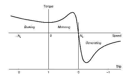
- The speed-torque curve extends to the second quadrant. The speed of the motor decreases. The braking torque makes the motor run at constant speed, arresting its tendency to rotate faster.
- During braking period speed is positive whereas torque become negaitve.
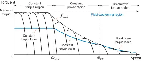
- Above image shows that speed torque relation of Induction motor where we can see that constant torque region is maintained at lower speed and the constant power region is maintained at higher speed or above the base speed.
- As the speed further increases back EMF value increases and which result in reduction in torque value.
- The amount of power required for accelration the vehicle from one speed to another is similar to power required for deaccelration between same speed.
- Torque speed characterstics for deaccelration of motor is just mirror image of above charcterstics henc at higher speed the torque genration is minimum.
- Peak torque for acceration > Peak torque for deacceleration.
- As motor working in field weakening region (Greater than base speed or at constant power region) at higher speed torque genrated is less as compare to lower speed,(Torque value is compromised).
- Therefore braking torque is always less than the accelration torque which produce during accelration or starting of motor.
- This is the one of limitation of motor due to which Regenerative braking is cannot happen so effectively that we can get all the power back to the battery.
HowElectric and Mechanical braking is coordinated.
Brake control strategies
1. Series brake : - We are applying only one brake (regenrative or mechanical) at a time.
2. Paralle brake : - Applying brake paralle to each other or at same time applying both the brakes.
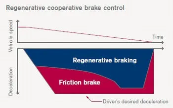
EDIB: - ELECTRIC DRIVEN INTELLIGENT BRAKE this applied in NISSAN LEAF car where paralle braking happened ,
During higher speed regenrative and mechanical brake applied equally and at lower speed torque is higher hence regenrative braking percentage is increased and maximum KE of motor is converted into the electrical energy. same showed in below
 .................
2.Make a MATLAB program which plots contour of given motor speed, torque and efficiency values. Attach the code as a .m file attach a screenshot of all the plots.
Answer:-
https://drive.google.com/file/d/1XjC06vhk609t7B335ND2BY_1OBTRDAXa/view?usp=sharing
clear all
close all
clc
% SPEED ARRAY
w = linspace(0,1000,100);
% TORQUE ARRAY
T = linspace(0,300,100);
% LOSS COEFFICIENTS
kc = 0.18; % COPPER LOSSES
ki = 0.006; % IRON LOSSES
kw = 0.000015; % WINDAGE LOSSES
% MESHGRID
[X,Y] = meshgrid(w,T);
copper_loss = (Y.^2)*kc;
iron_loss = X*ki;
windage_loss = (X.^3)*kw;
K = 20;
output_power = X.*Y;
input_power = (copper_loss)+(iron_loss)+(windage_loss)+(output_power)+K;
Eff = (output_power)./(input_power);
n = linspace(0.7,0.98,15);
contourf(X,Y,Eff,n);
%surf(X,Y,Eff);
title('SPEED TORQUE CHARACTERISTICS')
xlabel('SPEED rad/s')
ylabel('TORQUE N-m')
zlabel('efficiency')
Code Explanatn :-
- Defined speed array and the torque array using linspace.
- defined value of lossed coefficient.
- Meshgrid command is used to putting the value of speed and torque array in [X Y] dimension or in grid.
- Dot product is required for array as it is not a single number it is array hence whole array should get multiply.
- calculating output power (T *w or X.*Y),
- Calculating input power using formula and then efficiency.
- n= linspace ( ) is used to scaling the efficiency axis.
- plot contour between X Y & efficiency usinf command contourf(X,Y,Effi,n).
- We can also plot using surf(X,Y,Effi),both results are given below.
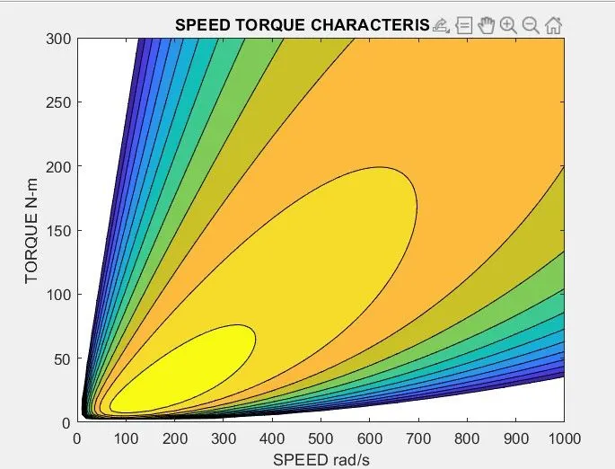
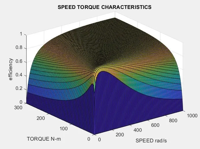
From the graph we can conclude that at particular toruqe and speed the efficiency of the motor is maximum.