Week-11 Challenge: Braking
QUESTION:1
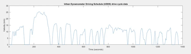
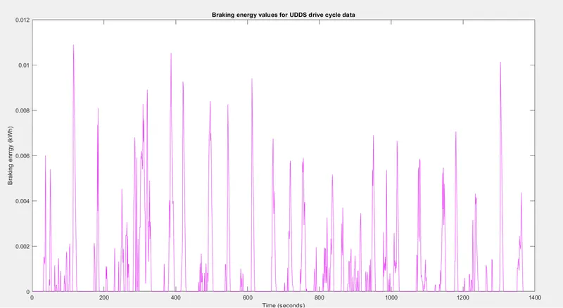
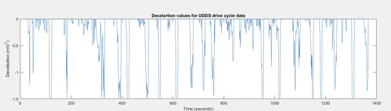
For a defined driving cycle, calculate the energy required for braking
The cycle simulates a urban route of 7.5 mi (12.07 km) with frequent stops. The maximum speed is 56.7 mph (91.25 km/h) and the average speed is 19.6 mph (31.5 km/h).
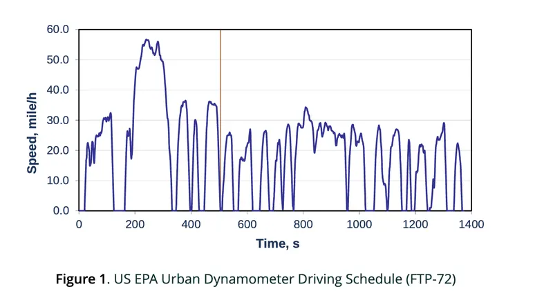
The cycle consists of two phases: (1) 505 s (5.78 km at 41.2 km/h average speed) and (2) 867 s. The first phase begins with a cold start. A weighting factors of 0.43 and 0.57 are applied to the first and second phase, respectively. Emissions are expressed in g/mile or g/km.
here are two kinetic types of energy that are involved in a moving car:
Linear and rotational kinetic energy,
The deceleration from V1 to V2 will reduce the energy. This energy is being saved in hybrid and electrical cars as regenerative energy.
The linear energy change is equal to:
Ke linear chang=12mv12−12mv22">𝐾𝑒 𝑙𝑖𝑛𝑒𝑎𝑟 𝑐ℎ𝑎𝑛𝑔=12𝑚𝑣21−12𝑚𝑣22Ke linear chang=12mv12−12mv22
And rotational energy change is equal to:
Ke rotatinal change=12I1ω2−12I2ω2">𝐾𝑒 𝑟𝑜𝑡𝑎𝑡𝑖𝑛𝑎𝑙 𝑐ℎ𝑎𝑛𝑔𝑒=12𝐼1𝜔2−12𝐼2𝜔2Ke rotatinal change=12I1ω2−12I2ω2
And V=rω=dω/2 and ω=V/r"> 𝑉=𝑟𝜔=𝑑𝜔/2 𝑎𝑛𝑑 𝜔=𝑉/𝑟 V=rω=dω/2 and ω=V/r with r being the radius of the wheel, r = d/2.
However, because of small "I" of the wheels compared to the mass of the car, the contribution of the wheel's change of energy is not significant.
MATLAB PROGRAMME
Sometimes after accelerating you can't reach the maximum torque. The reason is that no matter how much the current loop wants to increase current (proportional to torque) by increasing the PWM duty cycle of the power stage, the Vmotor is too close to Vbemf and therefore current can't increase more.
Whenever Friction torque + Additional loads = Motor Torque, the load remain in equilibrium (does not move, or moves under constant speed). Whenever Friction torque + Additional loads < Motor Torque, the load accelerates (Motor torque - Friction torque - Additional loads = Acceleration torque > 0). Al high speeds, the BEMF is so close to Vbus that the applicable Motor torque gets limited. Then, the bigger the Friction torque + Additional load is, the smaller the Acceleration torque becomes.
This can also occur if acceleration or speed is limited by some reason.
This situation does not occur at beginning of an acceleration because most of the torque is used to increase the kinetical energy of the load (and motor). But when the speed is already high and no extra load is applied it is not possible to increase the torque.
Maximum achievable torque depending on motor speed
Recalculate this based on your motor parameters.
Compensation for electric mobility throttles
This situation creates a bad feeling that at high speeds the throttle does not work correctly.
The user feels that it releasing the throttle does not reduce motor force!
The proposed solution is to add a torque demand limitation based on speed.
- Will improve user feeling when releasing brake when the vehicle is already accelerated.
- Will limit vehicle top speed (safety)
the force and moment generating characteristics of the tyre were discussed and it was shown how the braking force generated at the tyre contact patch depends on the value of the slip ratio which varies from zero for a free rolling wheel to unity for a braked and fully locked wheel. In this section we are not so much concerned with the tyre, given that we would be using a tyre model interfaced with our full vehicle model to represent his behaviour. Rather we now address the modelling of the mechanisms used to apply a braking torque acting about the spin axis of the road wheel that produces the change in slip ratio and subsequent braking force.
Clearly as the vehicle brakes, as shown in Figure 6.26, there is weight transfer from the rear to the front of the vehicle. Given what we know about the tyre behaviour the change in the vertical loads acting through the tyres will influence the braking forces generated. As such the braking model may need to account for real effects such as proportioning the braking pressures to the front and rear wheels or the implementation of ABS. Before any consideration of this we need to address the mechanism to model a braking torque acting on a single road wheel.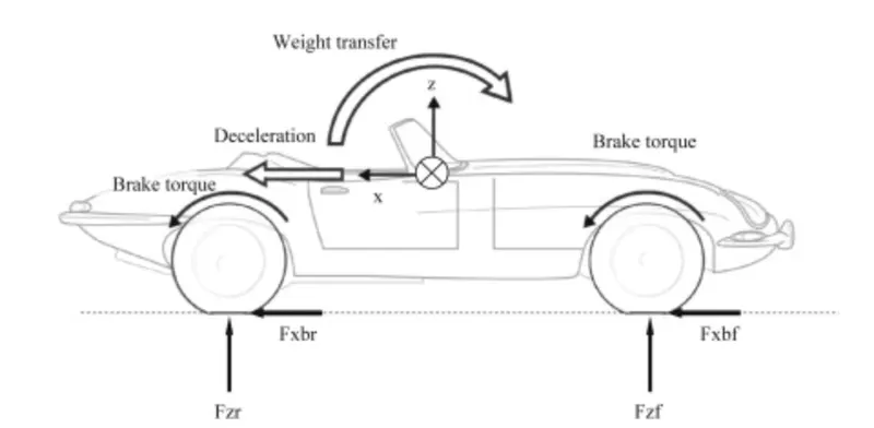
where
-
n = the number of friction surfaces(pads)
-
μ = the coefficient of friction between the pads and the disc
-
p = the brake pressure
-
A = the brake piston area
-
Rd = the radius to the centre of the pad
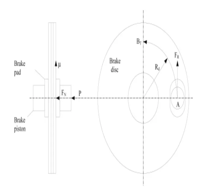
Note that depending on the sophistication of the model, the coefficient of friction μ may be constant or defined as a run-time variable as a function of brake rotor temperature. Note also that brake pad/rotor friction is substantially more Newtonian than tyre friction and thus subject to much less complication than the rubber friction previously discussed. Some kind of friction model is still needed to prevent the direct application of a braking torque spinning the wheel backwards, which does not happen in practice. Figure 6.28 shows typical brake friction vs temperature characteristics for different brake rotor materials. Brake rotor temperature, T, can be calculated using the differential equation
-
T0 = Initial brake rotor temperature (K)
-
ω(t) = Brake rotor (rads s−1)
-
t = time (s)
-
h = Brake rotor (W m−2 K−1)
-
Ac = Convective area of brake disc (m2)
-
Tenv = Environmental temperature (K)
-
m = mass of brake rotor (kg)
-
c = specific heat capacity of brake rotor (J kg−1 K−1)
-
BT(t) = Brake torque (Nm)
RESULT: So Electric motor can't develop braking torque at high speed similar to starting, because Braking Torque of an EV Motor is not as high as the Acceleration Torque. Therefore Regenerative braking is cannot happen so effectively that we can get all the power back to the battery.
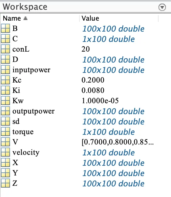
Question-3- Make a MATLAB program which plots contour of given motor speed, torque and efficiency values. Attach the code as a .m file attach a screenshot of all the plots.
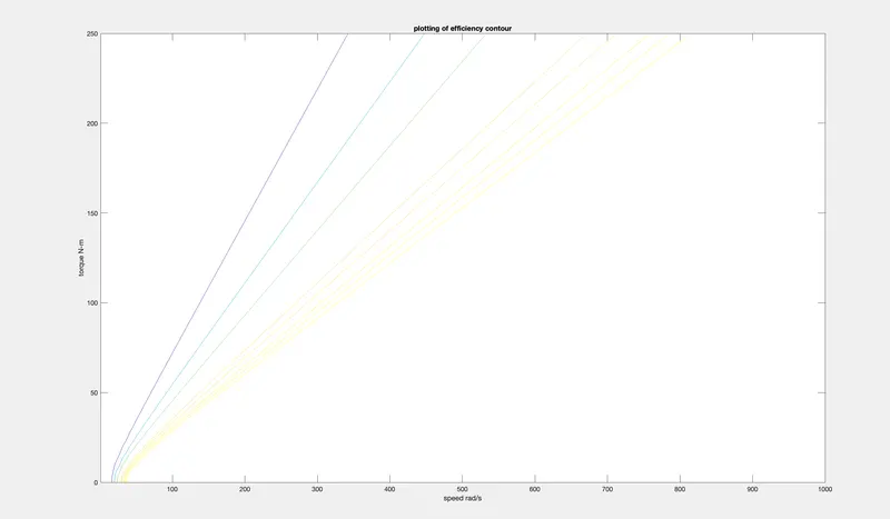
RESULT:
Hence the result of the plots contour of given motor speed, torque and efficiency values has been plooted and submitted