Week-11 Challenge: Braking
1. For a defined driving cycle, calculate the energy required for braking.
Drive Cycle: A driving cycle is a series of data points representing the speed of a vehicle versus time. It has acceleration and decceleration to increase and decrease the speed with respect to time. The decceleration points are the braking points which is to calculate the braking energy.
Braking Energy: The braking energy is the kinetic energy which stops the motion of the vehicle. It have a formula
Braking energy = 0.5 * m * v^2
Where,
m = Mass of the vehicle in kg,
V = velocity in mps or m/s.
So, Here we can calculate the Energy required for braking.
Here the Calculation is done in Excel Sheet:
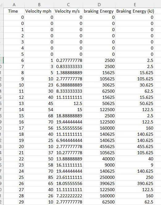
The above figure shows the time (sec), Velocity in mps and m/s, braking energy and which is done in kilo joules. The braking energy energy in KJ is to calculate by divided by 1000 as the value of in braking energy.
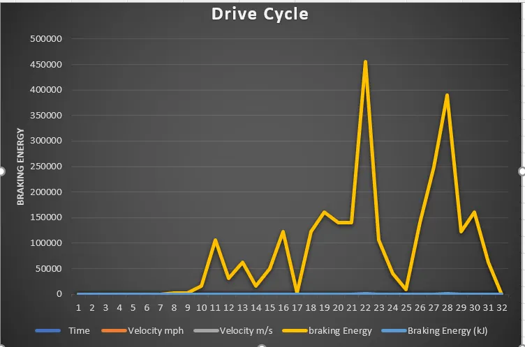
The graph shows the Braking energy is increases which when brakes are applying and vehicle comes to rest position after the kinetic energy will release in this manner.
Assumes the mass of the vehicle is 1250kg
braking energy = 0.5 * 1250 * (10-25)^2
= 140625
braking energy in (kJ) = 140.625 kJ.
This is the energy required for braking is calculated.
2.Why electric motor can’t develop braking torque at high speed similar to starting? How electric and mechanical brakes are coordinated?
Pull-up Torque:
The pull-up torque is the minimum torque developed by an electrical motor when it runs from zero to full-load speed (before it reaches the break-down torque point).
When a motor starts and begins to accelerate the torque in general will decrease until it reach a low point at a certain speed - the pull-up torque - before the torque increases until it reach the highest torque at a higher speed - the brake-down torque - point.
The pull-up torque may be critical for applications that needs power to go through some temporary barriers achieving working conditions.
Brake-down Torque:
The Brake-down Torque is the highest torque available before the torque decreases when the machine continues to accelerate to working conditions.
Braking Mode:
In the Braking mode, the two leads or the polarity of the supply voltage is changed so that the motor starts to rotate in the reverse direction and as a result the motor stops. This method of braking is known as plugging. This method is used when it is required to stop the motor within a very short period of time. The kinetic energy stored in the revolving load is dissipated as heat. Also, motor is still receiving power from the stator which is also dissipated as heat. So as a result of which motor develops enormous heat energy. For this stator is disconnected from the supply before motor enters the braking mode.
If load which the motor drives accelerates the motor in the same direction as the motor is rotating, the speed of the motor may increase more than synchronous speed. In this case, it acts as an induction generator which supplies electrical energy to the mains which tends to slow down the motor to its synchronous speed, in this case the motor stops. This type of breaking principle is called dynamic or regenerative breaking.
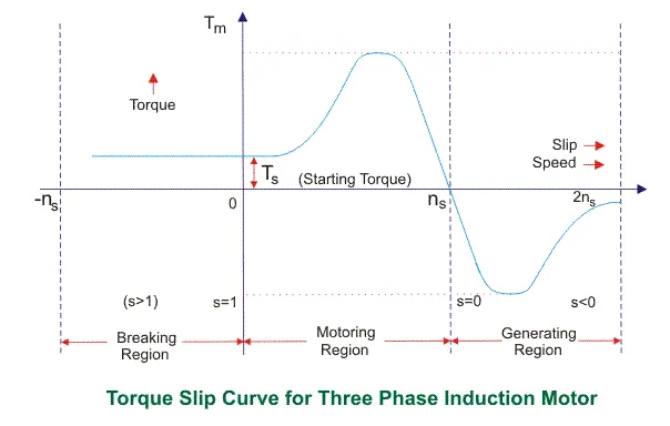
Regenerative braking takes place whenever the speed of the motor exceeds the synchronous speed. This baking method is called regenerative baking because here the motor works as generator and supply itself is given power from the load, i.e. motors. The main criteria for regenerative braking is that the rotor has to rotate at a speed higher than synchronous speed, only then the motor will act as a generator and the direction of current flow through the circuit and direction of the torque reverses and braking takes place.
Peak acceleration torque and peak decceleration torque are not equal for electric vehicle motors. The high torque will produce a low speed and the low torque will produce a high speed. So this is why electric motor can't develop braking torque at high speed.
How Electrical abd Mechanical Breaks are Coordinated:
Electro-Mechanical Brake (EMB) is the brake system that is actuated by electrical energy and has a similar design with the Electric Parking Brake (EPB). It uses motor power and gears to provide the necessary torque and a screw & nut mechanism is used to convert the rotational movement into a translational one. The main difference of EMB compared with EPB is that the functional requirements of components are much higher to provide the necessary performance for service braking such as response time. Such highly responsive and independent brake actuators at each wheel lead to enhanced controllability which should result in not only better basic braking performance, but also improvements in various active braking functions such as integrated chassis control, driver assistance systems, or cooperative regenerative braking. Although the EMB system has the potential for numerous advantages and innovations in braking, it has yet to be successfully introduced in series production mainly due to safety and cost concerns.
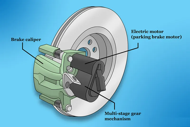
Although the EMB is conventionally thought of as a solution for oil-free braking system, the EMB system introduced in the current paper includes a hydraulic piston to make several functions possible. First, the hydraulic system allows for a mechanical back-up mechanism that leads to increased reliability. Second, the clamping force for braking control can be measured with a pressure sensor. And finally, the dual piston structure proposed in the current paper, which leads to amplification of the force transmission, allows for the design of lower specification and higher cost effective motor and gear components.
This new concept of EMB is termed the hEMB (hybrid EMB) in this paper. This study proposes to use a combined system of front hEMB and rear hydraulic caliper. This type of system has the potential of providing many advanced braking functions without the high cost associated with fully electric four wheel brake by wire systems. Prototypes of hEMB actuators were made and attached in a test vehicle. Results of bench and vehicle tests will be given to show the functionality of the system.
The combination of electric and mechanical braking is more efficient then only mechanical braking.
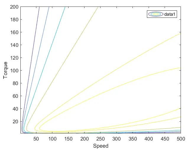
3. Make a MATLAB program which plots contour of given motor speed, torque and efficiency values. Attach the code as a .m file attach a screenshot of all the plots.
An efficieny map of an electric motor is a contour plot of speed and torque.
% A Motor efficiency contour.
clc
clear all
close all
x=linspace(1,500); % Motor speed in rad/s
y=linspace(1,200); % Motor torque in N-m
% Motor loss constants
% Copper losses constant
Kc = 0.3;
% Iron losses constant
Ki = 0.008;
% Windage losses constant
Kw = 0.00001;
% Constant motor losses
Con = 20;
[x,y] = meshgrid(x,y);
% power equation power = torque*speed
outputpower = (x.*y);
% Calculating copper losses
A = (y.^2)*Kc;
% Calculating iron losses
B = x*Ki;
% Calculating windage losses
C = (x.^3)*Kw;
Inputpower = (outputpower + A + B + C +Con);
% Efficiency
z = outputpower./Inputpower;
% Mapping the contours of the efficiency
v = [0.5,0.6,0.7,0.8,0.9,0.92];
% plotting the contour
box off
grid off
contour(x,y,z,v);

legend("show")
[c,h] = contour(x,y,Z,V)
xlabel = ('speed');
ylabel = ('torque');
hold on
Result: