Week-11 Challenge: Braking
1:For a defined driving cycle, calculate the energy required for braking.
braking force formula .
The following formula is used to calculate the braking force of a car given a speed, weight, and stopping distance.
F = (0.5*m*v^2)/d
- Where F is the required force to stop in distnace d
- m is the mass of the car
- v is the velocity of the car before braking
- d is the stopping distance
braking force :
Alternatively known as Brake Power, the braking force refers to the total amount of force exerted on a moving body that causes it to slow to a halt.The bodyor the vehiclemust be traveling at a known constant velocity for this force to be calculated correctly. The brake force is measured in newtons “N.”
For us to calculate the braking force, we must first know the moving body’s constant speed, weight, and stopping distance. After acquiring these factors, apply the equation
Kinetic Energy = Force x Distance
First, we calculate the kinetic energy. For the brake to stop a car, the kinetic energy has to be a zero. And so, the car’s speed and weight (divided by the value of gravity) are used to calculate it
½ x Mass x Velocity2
The accuracy of these calculations is limited by several conditions, though. If the surface of the road is icy or wet, such parameters can change completely.
Drive-cycle
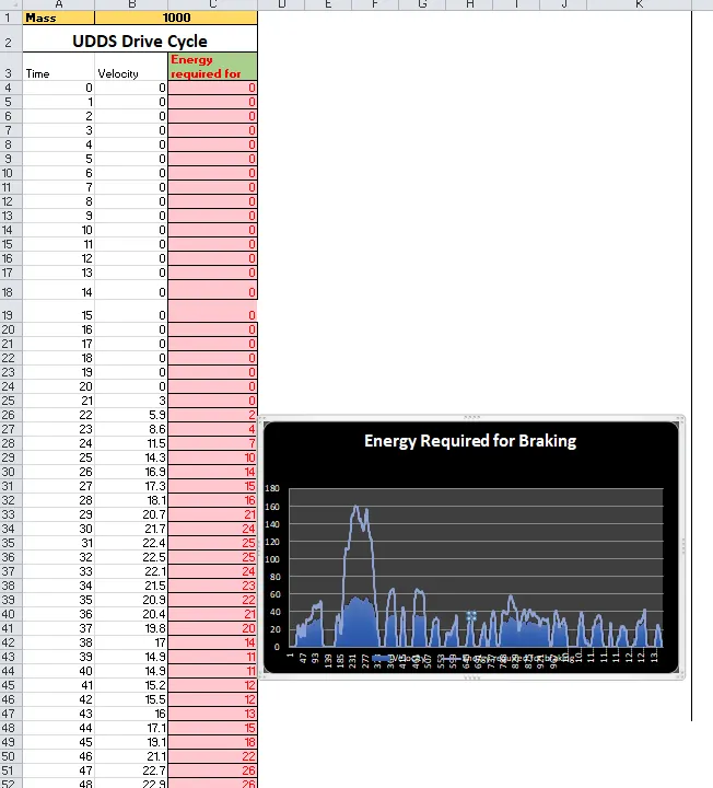
here we can calculte the braking energy for each time seconds slowdown - and stop the vehicals in this case we calculate the braking energy by using UDDS drive cycle
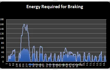
here we consider the value of mass of vehicals is 1000 and other value may take velocity with respects to time instants we performs such calculations of braking energy .
2:Why electric motor can’t develop braking torque at high speed similar to starting? How electric and mechanical brakes are coordinated?
This situation occurs only when the vehicle is at high speeds because the motor will be running at the constant power region. In the constant power region, the torque of the motor reduces and so the motor cannot develop the braking torque which is equal to the torque that occurred during low speed at the constant torque range. The torque vs speed plot of a vector control induction motor is given below
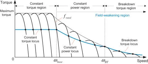
From the above characteristic curves of the motor that is seen that the torque of the motor remains high at low speeds and reduces as the speed increases
Since the electric motor cannot develop braking torque at a high speed similar to starting
Types of braking
Mechanical braking
In mechanical braking, the frictional force between the rotating parts and brake drums provide the required brake. Mechanical equipments such as brake linings, brake shoes and brake drums are required. This type of braking require frequent maintenance.
Mechanical braking
In electric braking, the motor is made to work as generator. So it produces a negative slip and negative torque (braking torque). This is achieved by suitably changing the electrical connections of the motor. Whether mechanical or electric braking, the braking, of the drive should be such as to stop the motor at the specified point of time and location, for reasons of safety. The electric braking may be required due to the following reasons.
- If a motor running at some speed is disconnected from the input supply, the only opposing torque will be the load torque. The motor will stop only after the kinetic energy stored in its inertia is dissipated. When either the load torque is small or the inertia is large, the motor takes long time to stop. In applications requiring frequent stops, the stopping time must be decreased by introducing additional opposing torque by use of electric braking.
- In some important applications such as traction, rapid emergency stops are essential to prevent accidents. The electric braking is mainly used to achieving quick and very smooth stops.
- Low efficient
- The energy of the rotating parts is wasted as heat in friction.
- It require frequent maintenance like adjustment of brakes, replacement of brake linings. They are prone to tear & wear.
- Depending upon the conditions the braking may not be very smooth.
- This braking is applied to hold the system at any position.
- Brake drum, brake shoes and brake linings are needed.
- High efficient method.
- The energy of the rotating parts can be converted to electrical energy which can be utilized or returned to the supply mains.
- It require very little maintenance because of absence of mechanical equipments.
- Braking is very smooth, without snatching.
- It cannot produce holding torque. It requires electrical energy for operation.
- Equipment of higher rating than the motor rating may. be needed in certain types of braking.
Compared to the mechanical braking, electric braking is highly efficient and requires low maintenance. Nevertheless, braking can result in stressful electrical and mechanical transients . Therefore, the braking system must be designed to ensure effective and safe operation.
Coordination of mechanical and electrical b raking in Ev
Two types of brake control strategies are used to organise the electrical brake and mechanical brake they are,
• Series control strategy
• Parallel control strategy
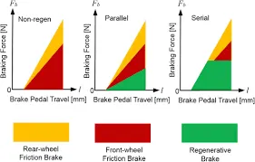
The comparison of the control strategies is shown in the below figure.
In the figure, it is seen that, according to the amount of brake pedal travel of the vehicle,
the mechanical brakes and regenerative brake are employed.
parallel control strategy :
when the brake is applied according to brake pedals travels and front wheel brake the rear wheel frictions brake
and regenrative brake is employed simulataniously higher travels brake and highers the amount of braking will be done
The following energy is distrubuted in following practice
Rear wheel friction brake ---- front wheel friction brake ---- regenrative braking
series control strategy
When the brake is applied according to the brake pedal travel the front wheel friction brake, the rear wheel friction brakes and the regenerative brakes are applied one after another. As the braking requirement increases the frictional brakes are used subsequently.
For low speeds of the vehicle, regenerative braking is used but it may be limited according to the SOC (state of charge) of the battery.
As the speed of the vehicle increases the rear wheel frictional brake will be employed if the braking requirement is not done but then the front wheel frictional brake is also used.
The coordination of the series control braking can be done with the choice to the comfort of braking (or) energy storage.
EDIB is a brake control strategy which is developed by NISSAN. It is a type of parallel braking which can be seen in the below image.
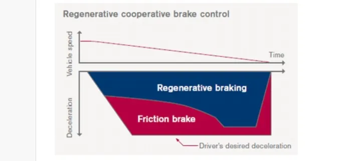
The above image shows that the frictional brake and the regenerative brake are used simultaneously at higher speeds of the vehicle At low speed the torque of the motor is high and so the regenerative brake has a higher braking part than the frictional brakes
Brif working of EDIB
When the driver steps on the brake pedal, the stroke sensor detects the operation of the brake. That report is communicated to the ECU and controls the motor. The motor engages the piston through the ball screw and increases the friction brake's pressure (hydraulic pressure). Through optimum control of the friction brake's hydraulic pressure, the energy regeneration result is maximized.
3:Make a MATLAB program which plots contour of given motor speed, torque and efficiency values. Attach the code as a .m file attach a screenshot of all the plots.
matlab program
% matlab programs plotting the contur plots .
clear
close
clc
%speed array
w=linspace(0,1000);
% torque array
T=linspace(0,300);
%loss coefficients
kc=0.18; % coppeer losses
ki=0.006; %Iron losses
kw=0.000015; % windage losses
% meshgrids
[x,y]=meshgrid(w,T);
copper_loss=(y.^2)*kc ;
iron_loss=x*ki;
windage_loss=(x.^3)*kw;
k=20;
output_power=x.*y;
input_power = (copper_loss)+(iron_loss)+(windage_loss)+(output_power)+k;
Eff=(output_power)./(input_power);
n=linspace(0.7,0.95,10);
contourf(x,y,Eff,n);
title('speed torque characteristics ')
xlabel('speed rad/s')
ylabel('torquen N-m')
following plot is obtaining the after run program
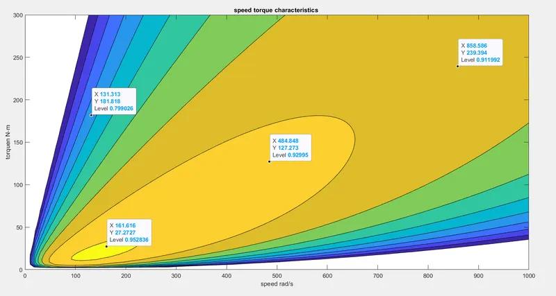
from the above graph we can see that particular speed and torque efficiency is maximum i.e 95 %
where the speed is x=151 rad/sec @24 N-m speed increase the efficiency of motor will reduce .