Week-11 Challenge: Braking
Que1) For a defined driving cycle, calculate the energy required for braking.
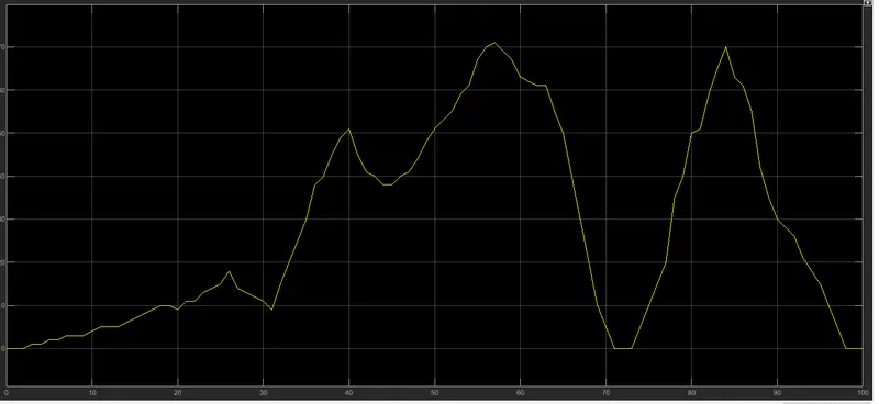
Answer- Drive Cycle- It is the plot of speed with respect to time. It is the reference for any vehicle which determines its range and emission.
Braking energy- Braking is the reducing the speed of any rotating machine. The energy release during the braking is due to the kinetic energy and friction.
Braking energy is kind of converted Kinetic energy so formula to calculate braking energy is,
1/2*m*V^2
where, V is the (final velocity - initial velocity).
So mass of vehicle is M1+M2, where M1 is Kerb weight+Payload & M2 is the Inertia of vehicle, here we consider 5% Inertia of total weight
| Kerb weight | Payload | Mass | Inertia | Total Mass |
| 800 | 200 | 1000 | 50 | 1000+50=1050 |
We have 5 deceleration points in our Excel sheel data of Drive cycle data. Therefore, we calculate Braking Energy as shown in Table given below.
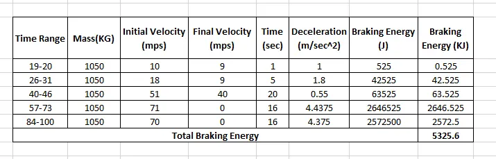

Therefore, total Braking Energy is calculated in our drive cycle is 5325.6 KJ.
Que2) Why electric motor can’t develop braking torque at high speed similar to starting? How electric and mechanical brakes are coordinated?
Answer-
Why electric motor can’t develop braking torque at high speed similar to starting?
For giving this answer we have to see following fig. which shows Torque & power relation with respect to the Speed.
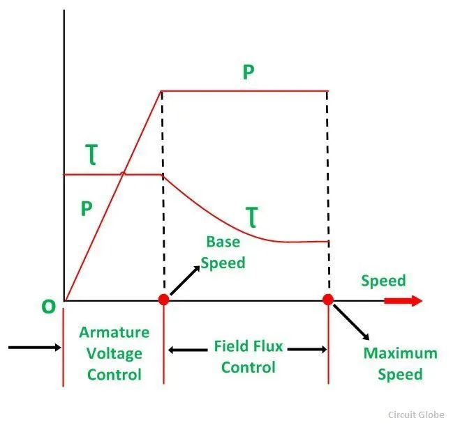
On the Y-axis Parameters are Torque and Power, & X-axis is Speed. Base speed also called as critical speed.
For speed below critical speed the region is Constant Torque where for region greater than critical speed is Constant Power.
For constant Torque Armature voltage control method use for the speed control & for Constant Power region Field Flux Control is used.
But this graph shows the Accelerating operation of the motor. For Deceleration or braking operation this Graph is mirror down where, Torque & Power is negative Y-axis & Speed remain same i.e. positive.
For Braking we can say that plot become,
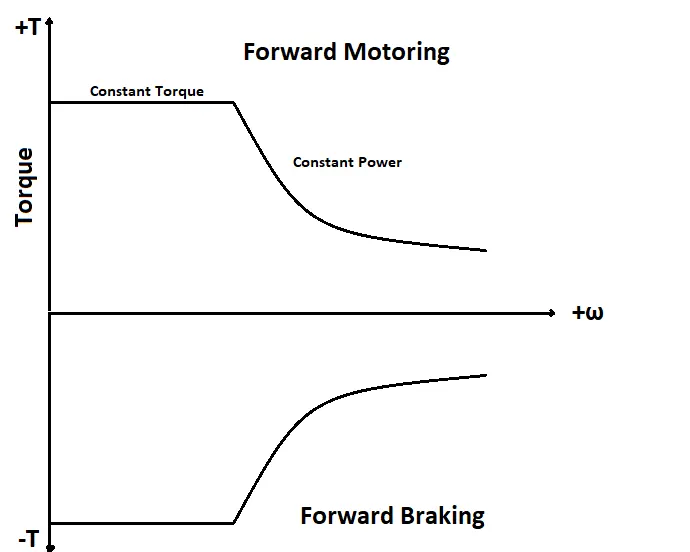
If for accelerating if torqur show '+ve' value then we can say that for braking this toque should be '-ve'. Beacuse while applying break we are already in field weakning region & operates in speed above critical speed, thus the accelerating torque is greater than peak deceleration torque.
The Torque after critical speed starts decreasing, motor voltage is kept constant and flux is weakened which drops with increase in the speed.Therefore, its torque also drops with the increase in the speed. Thus for acceleration it has High torque with low speed and for deceleration it has low torque for high speed. Therefore electric motor can't develop torque at braking similar to the starting.
Mechanical brake:
Mechanical brakes all act by generating frictional forces as two surfaces rub against each other. The stopping power or capacity of a brake depends largely on the surface area of frictional surfaces as well as on the actuation force applied.
As the brake pedal is pressed cam rotates, which pushes the brake shoes outwards and hence brake lining provided on the outer surface of the shoes rub against rotating the drum and hence slow down or stops the vehicles because the drum is connected to the wheels. As the pedal is released, due to retracting spring force shoes return to its original position.
Electrical brake:
The principle of working of this type of brake is to utilize the electromagnetic force on the brake shoes. It consists of an electromagnet, armature disc. An electromagnet is mounted on the backplate and armature disc is fed to the drum. This is simple in construction.
For working, electric current for the battery is utilized to energize the electromagnet which actuates the cams that expands the shoes. Thus, braking the wheel.
The magnet in the backing plate has 2 conductor wires which tap directly into the trailer wiring. When electricity is on, it magnetizes the brake magnet. The magnet is attracted to the drum face.
When it contacts this area, the friction causes it to rotate, which moves the actuating arm, and pushes the shoes out against the drum.
Those shoes have a special brake pad material on them that resists the heat caused by that friction. When the shoes press against the inside of the drum, they prevent the hub, and consequently the wheel that's touching the ground from spinning.
Co-ordination between mechanical and electric brake:
The brake distribution consists of two part which are electric brake called regenerative brake and mechanical brake
The brake force distribution must be uniform in the vehicle.
If the regenerative braking power requirement is more than the battery capacity or more than the regenerative capacity of machine then we must apply mechanical brake.
In practice this two braking are combine which gives flexible braking in the vehicle which is called brake control strategies.There are two brake control strategies,
1) Series- Brakes will be applied one after the another so which they are connected in series. Either one brake strategy at a time active Regenrative brake or Mechanical brake at a time.
2) Parallel- In case of parallel both the brakes are applied simultaniously i.e. both at a time.
Electric Driven Intelligent Brake-
After stepping on the brake padal, the system produces natural & adequate braking force that corresponds to the operation. The amount of energy regeneration also needs to be increased as much as possible. EDIB i.e. Electric Driven Intelligent Brake controls the regenerative brake and friction brake to support both of these requirements. Further, it also controls the reactive force from the pedal in order to unify the feelings when stepping down on the pedal and the sense of deceleration.
Que3) Make a MATLAB program which plots contour of given motor speed, torque and efficiency values. Attach the code as a .m file attach a screenshot of all the plots.
Answer-
clear all
close all
clc

speed= linspace(0,1000);
torque= linspace(0,500);

kc= 0.2;
ki=0.006;
kw=0.000010;
k=20;

[x,y] = meshgrid(speed,torque);
copper_loss= (y.^2)*kc;
iron_loss= x*ki;
windage_loss= (x.^3)*kw;

output_power= x.*y;
input_power= (copper_loss+iron_loss+windage_loss+output_power+k);
efficiency=(output_power./input_power);

n=linspace(0.7,0.95,10);
contourf(x,y,efficiency,n);
title('speed-torque efficiency')
xlabel('speed (rad/s)');
ylabel('torque (Nm)');
colorbar
Here in this program first 2 i/p were given. They are Speed & Torque using linespace command. Then the motor constant vakues are assigned namely copper loss, iron loss, windage loss and constant loss. We use meshgrid to evaluate function of two variables and three diamentional mesh surface plot.
Output power is calculated by multiplying speed and torque. then all the loss were calculated and the input power were also calculated. then comes the efficiency were calculated and Contour graph is plotted between speed, torque and efficiency.
For this M-script the contour is given below,
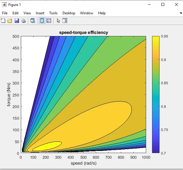
From this contour plot we observed that, the maximum eeficiency is at the centre where speed ranges from 100-300 rad/sec & torque ranges from 0-50 Nm. The Minimum Efficiency is at outer side of the contour where speed is about 900-1000 rad/sec & torque is about 150-500 Nm. So we say that maximum efficienct is at the lower speed and low torque.