Week-11 Challenge: Braking
- For a defined driving cycle, calculate the energy required for braking.
LETS KNOW ABOUT REGENRATIVE BREAKING FIRST:
Regenerative braking is a unique technique that is used in EVs to capture energy that the vehicle has due to its motion or, in other words, its kinetic energy that would have been wasted when the vehicle decelerates or comes to a standstill while braking. By taking a measure of the initial and final vehicle velocity, the amount of kinetic energy that is lost to braking can be calculated.
Urban drive cycles have a considerable amount of acceleration and decelerating periods due to traffic control systems in place around towns and cities, and therefore, when decelerating, significant energy is lost. However, with regenerative braking, this energy can be captured, and ‘waste’ energy can be harnessed and utilized for vehicle propulsion.
concept about how to to control speed of the vehicle and how how much energy is required to bring the vehicle to zero uff
when a car is moving with constant velocity we know it possess kinetic energy and to bring the vehicle /car to zero speed it need same amount of energy
therefore K.E=0.5*m*V^2
where m=mass of the car=1500kg
v=velocity of car =60kmph=16.66m/sec
so in order to bring the vehicle to reste it requires same amount of energy
therefore magnitude of work that needs to be done =0.5*1500*(16.66)^2
hence energy required to bring vehicle to zero speed =201186.7j=208.17kj
now we are going to calculate total break energy required over a defined drive cycle and in this case we are also going to calculate the average of break energy
step 1 we are going to make our own drive cycle in excel spread sheet ,
step 2 import the drive cycle data to matlab
step 3 write a matlab programme to calculate the total break energy and also plot the drive cycle data and break energy consumption data
below is the matlab programme and ploting of drive cycle and energy consumption
clear all
close all
clc
mass =1000;% mass of car
drive=xlsread('velocityandtime.xlsx');
t=drive(:,1) %time values
vel=drive(:,2);%speed values
for i=1:(length(vel)-1);
if vel(i)>vel(i+1)
BE(i)=0.5*mass*(vel(i)-vel(i+1))^2
end
end
fprintf('total brake energy is %d',sum(BE))
fprintf('Average brake energy is %d',mean(BE))
%plotting the results
figure(1)
subplot(2,1,1)
plot(t,vel,'linewidth',3,'color','b')
xlabel('time in sec')
ylabel('velocity in m/sec')
title('drive cycle')
subplot(2,1,2)
plot(BE,'linewidth',3,'color','b')
xlabel('time in sec')
ylabel('break energy')
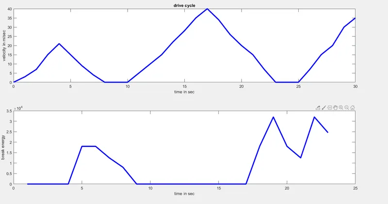

so the total break energy=sum of induidual break energy=8.41kj
module 2#
Why electric motor can’t develop braking torque at high speed similar to starting? How electric and mechanical brakes are coordinated
electric motor can’t develop braking torque at high speed similar to starting the reason will be explained
after operating at high speed back emf will also keep going on increasing this will reduce the flux which in turnreduces the current and hence the also gets torque gets affected /reduced
speed torque characteristice of electric motor
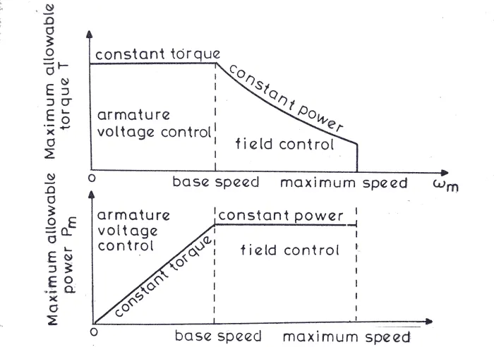
The diagram describes torque speed characteristics of a DC motor, however the same (or similar) is applicable to almost any electric motor.
1) The knee point here gives the rated speed
2) After the knee point the back EMF of the motor (which is directly proportional to the speed) increases such that the motor is no longer able to maintain the current supply. Any increase in current would require a proportional increase in supply voltage, which is generally fixed. Hence after this point the motor operates in constant power mode (The back EMF keeps on increasing and the current keeps on reducing)
3) As the current is reducing continuously, the motor torque also reduces in proportion.
To conclude, with speed increase beyond the rated speed, torque reduces, power remains constant. This continues till the maximum permissible speed, operation beyond which causes damage to the motor (Thermal and Mechanical).
in order to get maximum breaking torque we need an alternative method,these methods will be discussed below
limitation of brake torque
1 The brake torque is not large enough to meet the requested brake torque during intensive braking. Power dissipated by a front friction brake can be above 100 [kW].
2 The electric motor is unable to deliver a constant brake torque in the upper speed range. This means that the regenerative brake torque is speed dependent while the brake torque request is not.
3 At speeds around zero the brake torque of the electric motor drops to zero, due to low motor electromotive force.
4At stand-still friction brakes are better to hold vehicle (parking or holding assist).
5 Fail-safe function. In case the vehicle electronics malfunction the vehicle should still be able to come to a standstill, meaning a secondary brake system will be necessary.
6 RBS availability is limited by the charging condition of the energy storage system.
there are 2 break control strategies
SERIES AND PARALLEL RBS
PARALLEL RBS:
A parallel RBS works ‘in parallel’ with a friction brake system , meaning that the conventional brake system layout remains virtually unchanged. The brake pedal is mechanically coupled with the brake caliper and the brake pressure is proportional to the pedal travel and force. The electric motor (in generator mode) will add an additional brake torque. The driver’s brake pedal feel must be the same as a conventional brake system. That means, with the same pedal input (i.e. travel and force), the total brake force of the parallel RBS should reach the same deceleration as the conventional system . Therefore, the brake torque added by the generator can’t be very large and the recuperation potential is limited. A big advantage of parallel RBS is that there is no requirement for brake-by-wire . This means the brake control will be less sophisticated and the
SERIES RBS:
Series RBS realizes true blended braking between the friction brake system and the generator. The aim of the series or blended brake control is, achieving a speed independent constant deceleration for a given brake pedal position, thus ‘blending’ regenerative torque and friction brake torque. This is particularly important for high power generators, as they can be used for a large portion of the requested brake torque. The regenerative brake is prioritized over the friction brake system especially at low deceleration braking. When the brake pedal is further or faster depressed, the brake control unit (BCU) adds friction brake torque to gain deceleration. Strong electric generators need more modified brake systems. The brake pedal needs to be decoupled from the brake caliper leading to a so called brake-by-wire system. The control of a series RBS is more complex, but performs much better on optimizing energy recovery.
MODULE3#
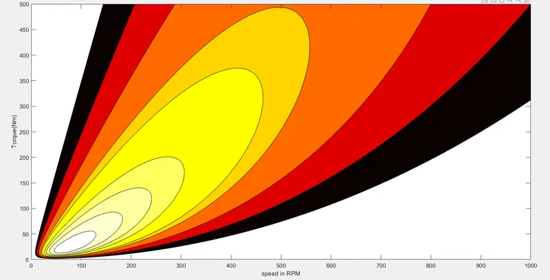
Make a MATLAB program which plots contour of given motor speed, torque and efficiency values. Attach the code as a .m file attach a screenshot of all the plots
ELECTRIC MOTOR EFFICIENCY:
Electric motor efficiency is the ratio between power output (mechanical) and power input (electrical). Mechanical power output is calculated based on the torque and speed required (i.e. power required to move the object attached to the motor), and electrical power input is calculated based on voltage and current supplied to the motor. Mechanical power output is always lower than the electrical power input, as energy is lost during conversion (electrical to mechanical) in various forms, such as heat and friction. Design of an electric motor aims to minimize these losses to improve efficiency.
in order to calculate efficiency we have deduct the losses thaT are associated with motor
copper losses=Kc*T^2
iron losses=Ki*W W=OMEGA=angular speed
constant losses=Cm
winding losses=Kw*W^3therefore total losses=[iron losses+copper losses+winding losses+motor constant losses]
Pout=TORQUE*SPEED
therefore effe=pout/pinput
effe =Pout/(Pout+losses)
clear all
close all
clc
%torque and speed inputs
speed=linspace(0,1000,350)
torque=linspace(0,500,500)
%motor loss input
Kc=0.1; % copper losses constant
Ki=0.001;% iron losses constant
Kw=0.0001;%winding losses constant
Cm=20; %motor losses constant
%Create 2-D grid coordinates with speed-coordinates defined by the vector W
%and Torque-coordinates defined by the vector T
[W,T]=meshgrid(speed,torque)
% calculate output power Pout=speed(W)*torque(T)
Pout=W.*T
%calculating total losses
Cop_L=Kc*T.^2;
Iron_L=Ki*W;
Wind_L=Kw*(W.^3)
Total_L=(Cop_L+Iron_L+Wind_L+Cm)
Pin=Pout+Total_L;
Efficiency=Pout./Pin;
%taking some higher values fromn the effeciency and will be stored in
%vector Z
Z=[0.74,0.80,0.84,0.87,0.88,0.90,0.91,0.92,0.93]
%contor poloting of efficiency w.r.t speed and torque
contourf(W,T,Efficiency,Z)
colormap(hot)
xlabel('speed in RPM')
ylabel('Torque(Nm)')
results of plotting