Week-11 Challenge: Braking
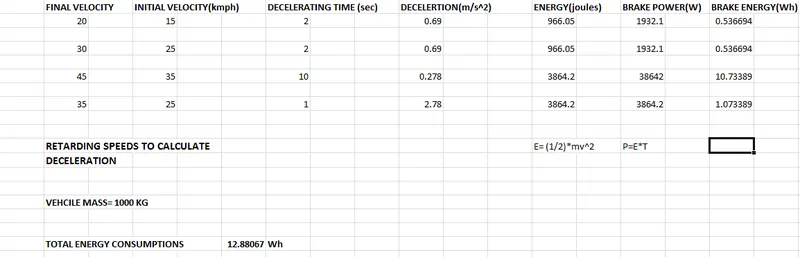
1)For a defined driving cycle, calculate the energy required for braking.
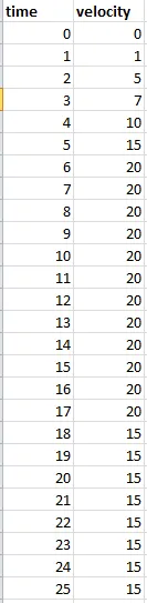
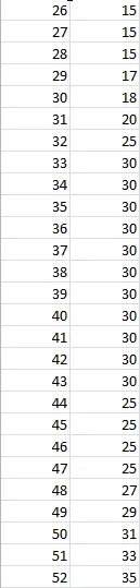
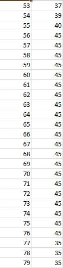
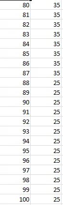
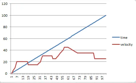
above is the random drive cycle created in the excel file.
Below is the graph for the above drive cycle:
2) Why electric motor can’t develop braking torque at high speed similar to starting? How electric and mechanical brakes are coordinated?
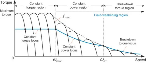
There are two operating reigons of the motor:
1) CONSTANT TORQUE REIGON
2) CONSTANT POWER REIGON
To apply the braking torque, we need the back emf value to be greater than that of the supply voltage. It can be done at no load speed or below no load speed with the help of variable voltage source, which can be achieved by power converter circuit.
Now, at lower speed or during the start of electric motor, it operates under the constant torque reigon which is the peak torque or we can say that maximum torque is needed during the start of the vehicle. Afterwards, as the speed of the motor increases, the motor operates in the constant power reigon and the torque required to drive the motor decreases. This is the reason for electric motors not developing braking torque at high speed.
COORDINATION BETWEEN ELECTRICAL AND MECHANICAL BRAKES:
1) Series Braking: It is type of braking inculcated in EV/HEV , where the mechanical or electrical brakes are applied one after the another to stop the vehicle or reduce its speed. Mehcanical brakes generally consists of frictional brakes, disc brakes,etc and electrical braking example can be regenrative braking.
2) Parallel Braking: The type of braking used in EV/HEV, where both mechanical and electrical brakes are applied together to stop or lower the speed of the vehicle.
Now, if we talk about mechanical brakes, while applying these brakes usually , the kinetic energy of the vehicle is disspated in the form of heat or other means. To overcome this heat dissipation effect , the regenerative braking is coordinated with it. Regenerative braking occurs when brake pedal is applied or the driver has its foot off from the acceleration pedal and at lower speed. So, during coasting mode or free run of the vehicle, the motor will behave as generator and produce back emf. Also, during free run, motor torque will oppose the load torque as the load is moving with inertia effect or gained momentum. Now, that back emf is the way to charge up the battery with the help of bidirectional power converter.
ELECTRIC DRIVEN INTELLIGENCE BRAKING:
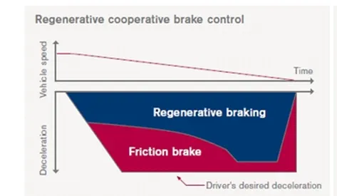
This braking design is from Nissan Leaf, which consist of both electromechanical braking. When the vehicle runs at higher speed and there is immediate need of braking, parallel braking is done means both the brakes are applied together which detected by the brake pedal. As the vehicle speed lowers down, the percentage distribution of the regenerative braking increases because torque is quite high at low speed, so major part goes to electric braking.
3)Make a MATLAB program which plots contour of given motor speed, torque and efficiency values. Attach the code as a .m file attach a screenshot of all the plots.
%MATLAB MODEL TO PLOT A CONTOUR PLOT FOR A GIVEN MOTOR SPEED, TORQUE AND
%EFFICIENCY VALUES
clear
close all
clc

%% HIGEN MOTOR VALUES ARE TAKEN FOR THE PLOTTING USED IN AN EV
%% The x-axis corresponds to the vehicle speed
%% The y-axis corresponds to the torque values
x= 0:1000 ; % setting the range for speed values
y= 0:300 ;  % setting the range for torque values


%% Allocating the motor loss constants
kc=0.2; %copper losses
ki=0.008; %iron losses
kw=0.00001; %windage losses
con= 20; % for constant motor losses


%% making a mesh
[X,Y]=meshgrid(x,y);
out_power=(X.*Y); %torque *speed = power
B=(Y.^2)*kc;   %copper losses
C=X*ki ;       %iron losses
D=(X.^3)*kw;   %windage losses

inp_power= out_power+B+C+D+con;
Z= out_power./inp_power;


%% setting the efficiencies for which the contour will be plotted
V=linspace(0.7,0.96,10);
box off
grid off
contourf(X,Y,Z,V);
xlabel('speed rad/s')
ylabel('torque N-m')
title(' SPEED TORQUE CHARACTERISTICS ')
Firstly, speed and torque value range of a motor specifications are taken as a array using linspace command with torque in y and speed in x-axis. After, motor loss constant values are allocated in the program which are given values from the motor specifications. Afterwards, meshgrid is created for speed and torque values, which is termed as a rectangular array. Following this, all the losses are calculated and then, input power is calculated which is summation of all the losses and output power. Finally, efficiency is calculated from the ouput power and then array of motor efficiencies which is given in the motor specifications is listed and contour plot is made.
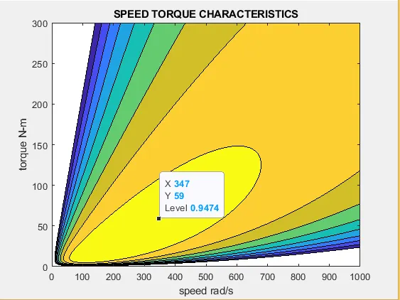
From the above plot, 94.74 IS THE BEST EFFICIENCY OBTAINED AT 347 rad/s and 59N-m torque.