Week-11 Challenge: Braking
1.For a defined driving cycle, calculate the energy required for braking?
Ans:-
The function of the braking system is to retard the speed of the moving vehicle or bring it to rest in the shortest possible distance whenever required. The vehicle can be held on an inclined surface against the pull of gravity by the application of a brake. Brakes are mechanical devices for increasing the frictional resistance that retards the turning motion of the vehicle wheels. It absorbs either kinetic energy or potential energy or both while remaining in action and this absorbed energy appears in the form of heat. While moving down a steep gradient the vehicle is controlled by the application of brakes. In this case, brakes remain in action for a longer period making it imperative to dissipate the braking heat to the atmosphere as rapidly as possible.
Automobiles are fitted with two brakes; the service or foot brake and the emergency or hand brake. The foot brake is used to control the speed of the vehicle and to stop it, when and where desired, by the application of force on the brake pedal. The hand brake, applied by a lever, is used to keep the vehicle from moving when parked. Hand brakes are called emergency brakes because they are applied when the service brake fails. Virtually all vehicles are now equipment with 4-wheel brakes. The front brakes must operate without interfering with the steering action.
The objective is to calculate the energy required for braking for a defined driving cycle.
The energy required to stop an electric vehicle is called as Braking energy.
We use two types of braking in electric vehicle:
1) Electric braking
2) Mechanical braking
The above two brakings are necessary to halt the vehicle from a given speed to zero speed.
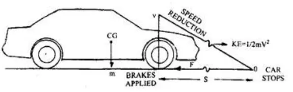
The energy required for braking is given as follows:`E = 1/2mV^2`
where,
m= mass of the vehicle in Kg
V= final velocity in m/s
Let us create a Drive cycle, which is generally a speed vs time graph.
The below snap shows the drive cycle.
Thus, the kinetic energy doubles as the weight doubles, but it increases four times as speed doubles
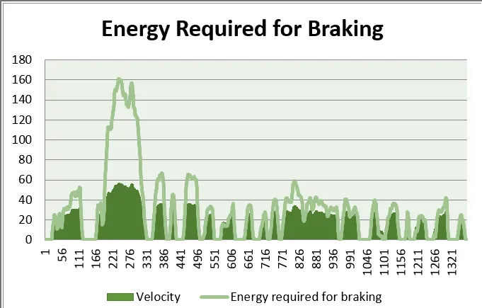
For the above data cycle we need to calculate the average Braking energy required. This can be done by converting the data points from drive cycle to the excel format as shown in below figure.
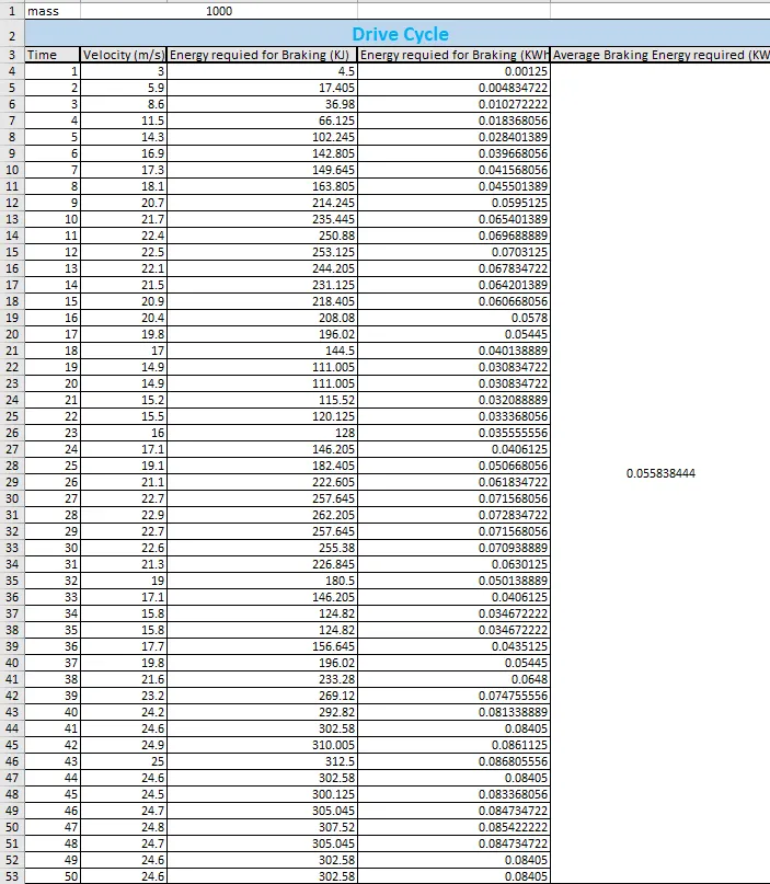
From the above excel sheet, we can calculate the braking energy required at various speed using the formula
`E=1/2mv^2`
Hence the average value of braking energy for the overall drive cycle is 0.05584 KWh.
2. Why electric motor can’t develop braking torque at high speed similar to starting? How electric and mechanical brakes are coordinated?
Ans:-
There are mianly 2 major reasons for a motor to develop a higher starting torque compare to braking.
1. Due To Transients:-
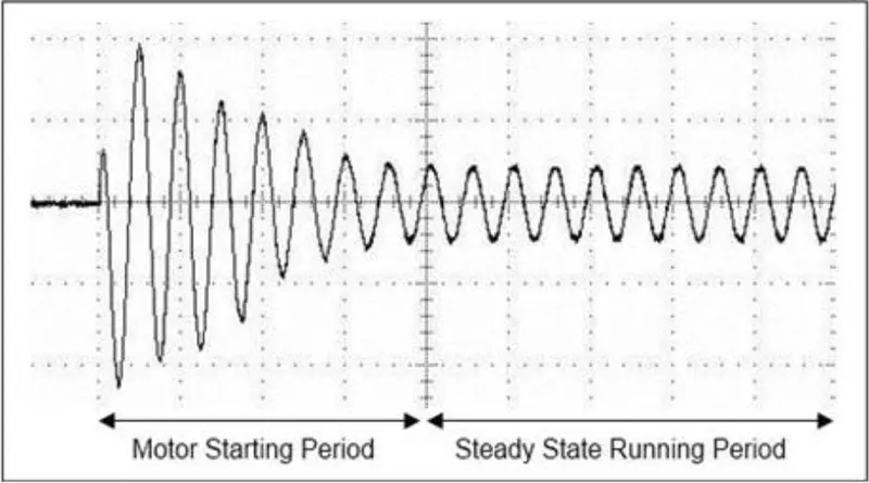
At the starting the motor, it draws a large current due Transient . As we know that torque is proportional to square of current, hence the torque value is also very high at this moment.
When brakes are applied to motor at that time current value recides within the range hence the Torque values is also recides within the range.
2. Torque speed characteristic:-
From Torque speed characteristic we know that when speed is increased torque should decrease to maintain the constant power. At the time of starting of motor, the speed is very low hence the value of torque is very high.Similarly, at the time of braking of a motor, the speed value is high hence there will be a low torque value present. Therefore at the time of motor braking, available value of torque will be lower. The braking operation happens in the motor which is been distributed as per proportion in the 'REGENERATIVE BRAKING' and the 'BRAKE ENERGY'.
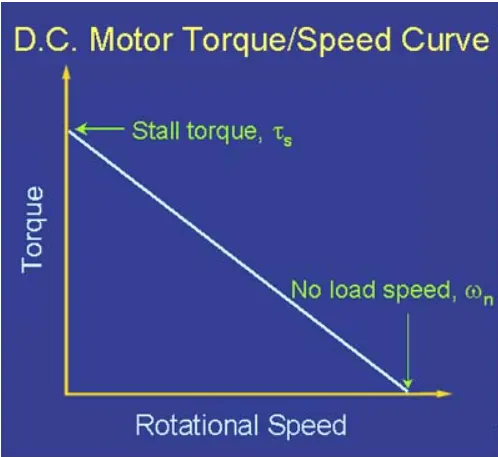
Hence we can conclude that the electric motor can’t develop braking torque at high speed similar to starting.
Coordination of electrical and mechanical brakes:
As we can see in several vehicles, the mechanical brakes uses the pedals which helps us to engage or disengage the brakes. Currently there are many life-saving braking technologies are available in the market such as EBD, ABS, BA and many more. All these latest technologies play a vital/major role in stopping the vehicle and coming back to the rest position at a high speed. In general when the driver applies the brakes the brake pads come closer to the disc connected with the driving disc. The brake pad usually offers inefficient braking.
There are two generic methods by which the vehicle could be braked in the ELECTRIC BRAKES.
1.Series - In this method, the mechanical braking and regenerative braking are applied one after another.
2.Parallel - In this method, the Mechanical Braking or the Regenerative Braking both are applied Parallely.
At lower speeds, regenerative braking are used and at the higher speeds mechanical brakes are used.
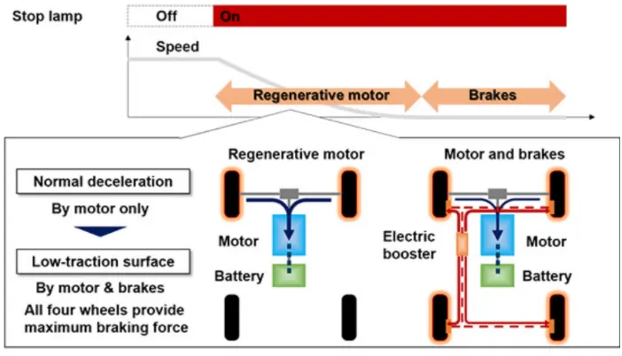
Whenever the brake pedal is pressed the hydraulic fluid reaches the brake piston and creates braking pressure on the wheels and the same kinetic energy is being used by regenerative braking for generating the more power using Bi-directional motor which operates as a generator while braking. An example of the proposition of mechanical braking and regenerative braking is NISSAN LEAF EDBI.
NISSAN LEAF EDIB (ELECTRONIC-DRIVEN INTELLIGENT BRAKING)
EDIB (Electric Driven Intelligent Brake) controls the regenerative brake and friction brake to support both of these requirements. Further, it also controls the reactive force from the pedal in order to unify the feeling when stepping down on the pedal and the sense of deceleration.
3. Make a MATLAB program which plots contour of given motor speed, torque and efficiency values. Attach the code as a .m file attach a screenshot of all the plots.
Ans:-
Here in the code first two inputs are given as speed and torque using linespace command.
Program Desciption:
- Here in the code first two inputs are given as speed and torque using linespace command.
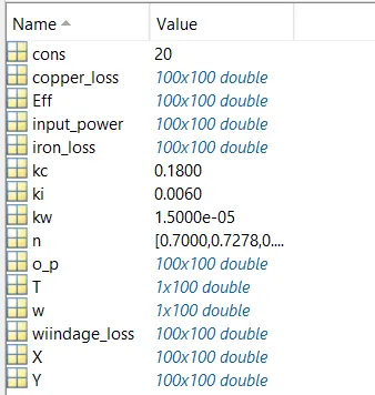
- Motor constants namely copper loss, Iron loss, Windage loss and motor constants are assigned.
- The meshgrid is used to evaluate functions 2 variables and 3-D mesh/surface plots.
- The output power is calculated by multiplying speed and torque.
- Then all the losses are calculated and the input powers are also calculated
- Then the efficiencies are calculated. And then contour graph is plotted between Speed, Torque and Efficiency.
- Title are given and labels are given.
Workspace:
Output Graph:
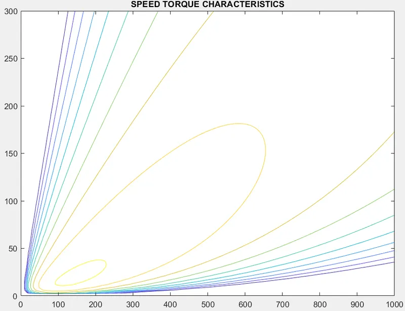
From the output graph, we can see that only at a particular speed and torque value, the efficiency is at maximum i.e. 95%.Where the Speed x = 151 rad/s @ 30 N-m Torque. As the Speed increases we'll get reduced efficiencies.