Week -2
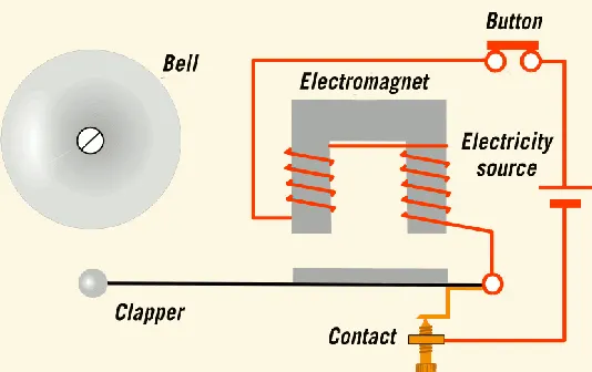
- Make a Simulink model of Doorbell using solenoid block with the following details:
Aim:
1.To make a simulink model of a doorbell using solenoid block.
2.To use a thermistor to sense the temperature of a heater & turn on or turn off the fan.
Condition:
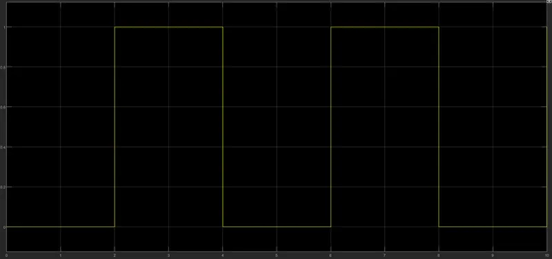
Switch is closed for 2 second and then released.
Objective:
1. Whenever the switch is closed the electromagnet receives electrical power from the battery and pulls the metal arm to hit the bell producing sound.
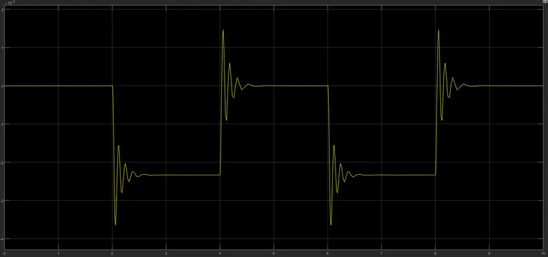
2. Create a situation where the switch is closed for 2 seconds and then released. Observe the physical movement of the plunger.
Block Used:
following blocks are used in Simulink to make this project
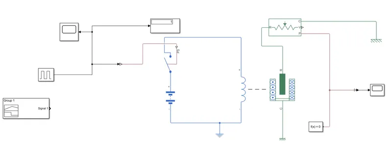
1.Pulse Generator
2.Switch
3.Battery
4.Electrical Reference
5.Solenoid
6.Mechanical Translational Reference
7.Ideal Translational Motion Sensor
8.Mechanical Translational Reference.
9.Solver Configuration
1.Door Bell Simulink Model:
Input pulse rate:
Cycle time 4sec bur pulse given as 2 second. The Graph will show the cycle.
Output:
Here can sense the Physical moment of the plunger as result shown below graph.
2. Use a thermistor to sense the temperature of a heater & turn on or turn off the fan as per below conditions:
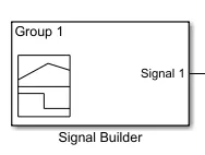
Singal Builder(input):
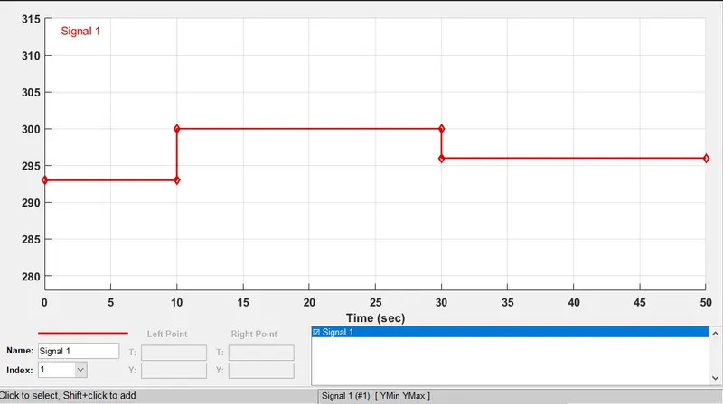
In signal builder giving input values as per given condition.
Given Inut:
At Point1 - Time O sec - Temperature - 293K,
At Point2 - Time 10 secs - Temperature - 293K,
At Point3 - Time 10 sec - Temperature - 300K,
At Point4 - Time 30 sec - Temperature - 300K,
At Point5 - Time 30 sec - Temperature - 296K,
At Point6 Time 50 sec - Temperature - 296K.
Controlled temperature source:
The Controlled trmperature source block represents and ideal source of thermal energy that is powerful enough to maintain specificd temperature diffrence across the sources regardless of the heat flow consumed by the system.
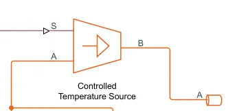
Connection A and B are thermal conserving ports corresponding to the sources onlet and outlet, respectively . Ports S in physical signal port, through which the control signal that drives the source is applied.
Thermistor
A thermistor is a type of resistor whose resistance is dependent on temperature, more so than in standard resistors. The word is a combination of thermal and resistor.
ADT
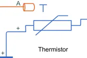
The Thermistor block represents an NTC thermistor using the B-parameter
equation.
NTC - Negative Temperature Co-efficient
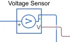
Voltage Sensor:
The Voltage Sensor block represents an ideal voltage sensor, that is, a device that converts voltage measured between two points of an electrical physical signal proportional to the voltage.
SIMULINK MODEL:
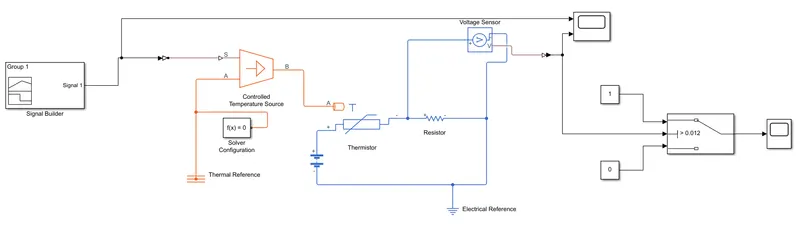
EXPLANANTION OF MODEL:
Inputs are given to the Signal Builder and Connected with Temperature Controlled Source for maintaining the specified temperature difference across the source. Then input temperature flows through thermistor
Thermistor is connected with Resistor, ensure that thermistor connected with positive terminal of the resistor and the voltage across the resistor is given by V(+) V(-), and the sign of the current is positive when flowing through the device from the positive to the negative terminal. This convention ensures that the power absorbed by a resistor is always positive.Connect the Positive terminal of Voltage Source to positive terminal of the thermistor and connect the negative terminal of Voltage Source to negative terminal of Voltage sensor and Resistor to get the values from the Voltage sensor(like series connection).
OUTPUT 1:
STUDY 1
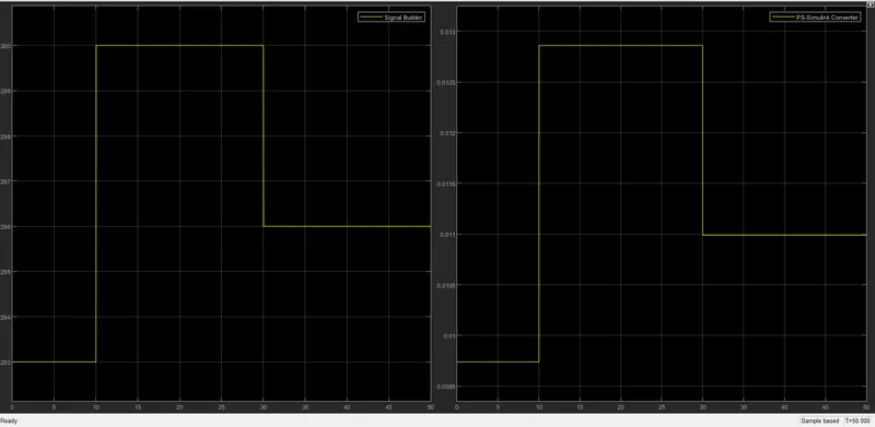
- From the above figure we can see that how voltage is changing with the change in temperature. Using this information, we can set condition for Fan to ON & OFF.
- If we observe the graph, we notice that from time 0 to 10 seconds when the temperature is 293K, Voltage is between 0.0095 and 0.01 and from time 10 to 30 seconds when the temperature is 300K, Voltage is between 0.0125 and 0.013 and from time 30 to 50 seconds when the temperature is 296K, Voltage is nearly 0.011.
- As mention in the objectives fan should be ON when the temperature is more than 25 degree Celsius i.e. 298.15K, from the above graphwhen voltage is more than 0.011 the Fan should get ON and when the Voltage is below 0.011. Fan should get OFF.
- This above Logic used to ON and OFF the Fan. To do this we have used a "Switch Block" that routes the Signal according to the conditions provided.
- The center port of "Switch Block" is connected to output of "PS-Simulink Converter" which gives the Voltage values. The top port of the "Switch Block" is connected to a "Constant Block" of value 1 and the bottom port of the "Switch Block" is connected to another "Constant Block" of value 0:
- The center port of "Switch Block" is the condition input which means that when the value from "Voltage Sensor Block" is more than the Threshold value in the "Switch Block" then it will pass the value 1 which we have specified in the top port of the "Switch Block". If the Voltage from the "Voltage Sensor Block" is less than the Threshold value in the "Switch Block" then it will pass the value 'O' which we have specified in the bottom port of "Switch Block". Here it acts like a Transistor in Real time Circuit.
- To set the reshold value of the "Switch Block", we have to Double click on the "Switch Block" and then we can change the value of Threshold. Since we want to be ON only when the temperature is 300K so the Threshold value is given as (0.011). so when the Voltage gets more than "0.011" the Switch will give value '1' as output which means Fan will be ONN and when Voltage get less than 0.011 the Switch will give value 'O' as output which certainly means Fan will get OFF.
- Now the output of "Switch Block" is connected to another "Scope Block" to get results.
STUDY 2
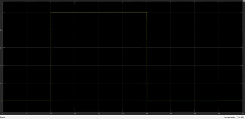
By Double clicking the "Scope Block we can observe the above Graph. Here we can clearly see that when temperature is 300K the Fan is ON and at remaining temperature the Fan is OFF.
CONCLUSION:
- Thus, both the objective was achieved successfully.
- Similar approach can be used for simulating other Physical Device using Simulink.
- Fan temperature was sensed by the thermistor in the Heater Model.