Project 1 (Mini Project on Vehicle Direction Detection
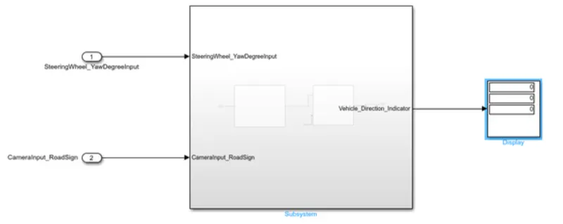
We have to create a model which suits the given requirements,We have the main model.
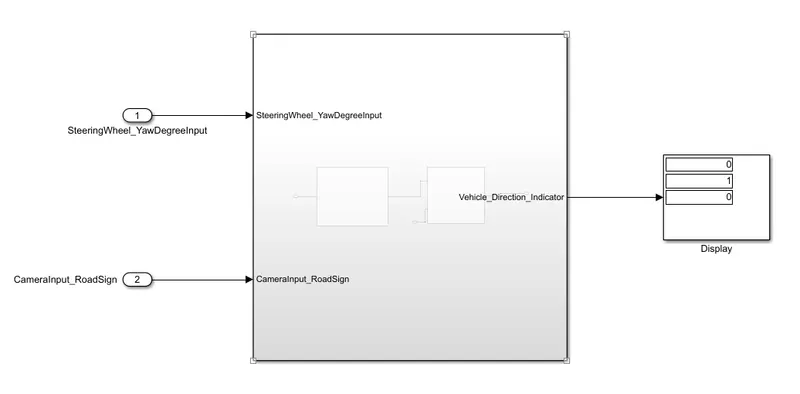
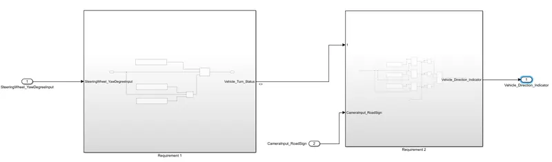
In Requirement 1:-
Steering wheel input as yaw rate (Signal name: SteeringWheel_YawDegreeInput) is
the input for this system.This is compared against 3 angular values, that is for each
for left turn, right turn & straight drive (Calibration Values: Right_Turn_AngularLimit,
Left_Turn_AngularLimit, Straight_Drive_Steering_Angle) to say which specific
direction the steering wheel is turning towards.Using switch blocks to compare &
develop this requirement. Keep this requirement in a subsystem & output of this
requirement is a local signal (Signal Name: Vehicle_Turn_Status).
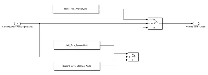
The steering wheel yaw angle is compared with the help of the switch block with left
tur,right turn and straight drive steering angle if it matches the condition in the switch
block it will pass the signal to the next subsystem,
In Requirement 2
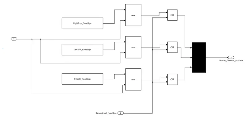
Inputs to this requirement are local signal from requirement 1 (Signal
Name: Vehicle_Turn_Status) & an input signal from camera (Signal
Name: CameraInput_RoadSign), which confirms the occurrence of a road
sign.Signal Vehicle_Turn_Status is compared against calibration values (Calibration
Values: RightTurn_RoadSign, LeftTurn_RoadSign, Straight_RoadSign), if each of
them is found equal, then each of the three corresponding output is compared
against the camera input signal,Using a logical OR operator block, Using mux block
the output from the operator is given and given to a
display,Vehicle_Direction_Indicator is the output represented by the display.
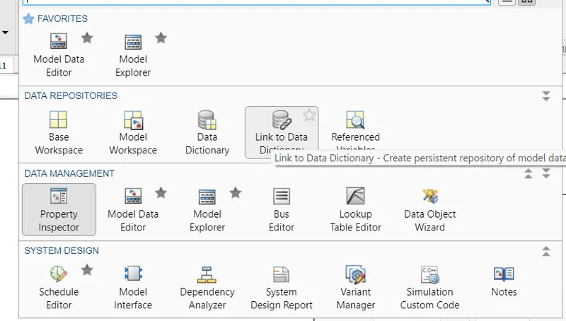
Next From the modelling pallete we have to link the dictionary to the model,we have
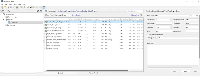
to create a sldd file for initiliazing the given datas,So creating a sldd file and entering
the values given above,
We are creating a sldd file pro1 in the location where we save our model,
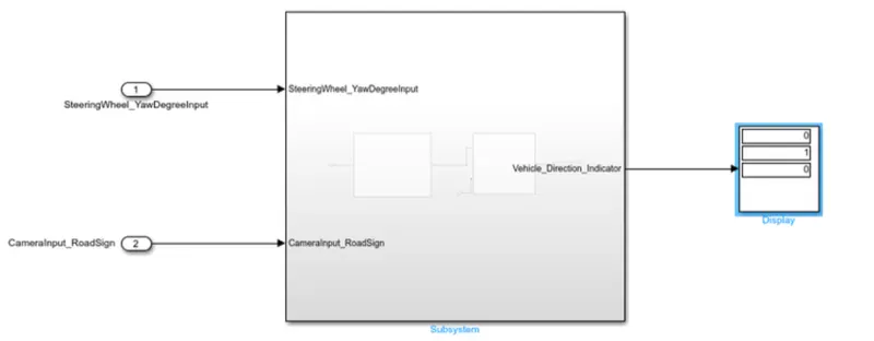
For right turn,
the output will be,
For left turn,
the output will be,
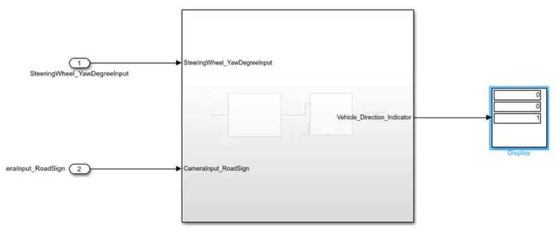
For straight direction ,
the output will be,
We can see from the table if the vehicle is taking a left turn ,the angle will be
negative value and for a right turn the steering angle will acquire a positive angle,and
the third condition is in straight direction where it will providing with a zero yaw
angle.
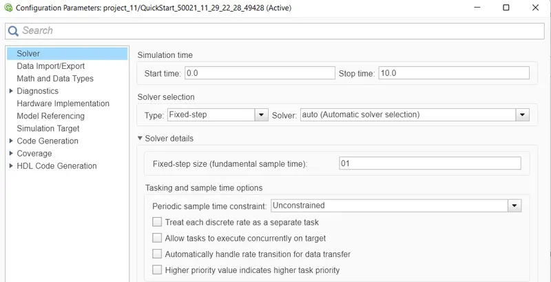
In the model configuration parameter table we can change the solver settings to
given values,the sample time is changed to 0.1 seconds for the model.
Generation of code for the model,From the apps icon we have the option to buld and
generate the model,
Results:
- The signs are in the way that Right, Left and Straight respectively.
- As the output is boolean, If we get the output as (0,0,1), Then the vehicle is moving in the straight drive.
- If the output as (1,0,0), Then the vehicle is taking in the Right turn.
- If the output is (1,0,1), Then the vehicle is taking the Left turn.
Conclusion:
Autonomous vehicles consists of various Advance Driver-Assistance System (ADAS) features. Vehicle Driection Detection is one the features of the vehicles.
Hence, created an Simulink model of Vehicle Direction Detection as per the Requirement data