Week-11 Challenge: Braking
- For a defined driving cycle, calculate the energy required for braking.
A brake is a mechanical device that inhibits motion by absorbing energy from a moving system. It is used for slowing or stopping a moving vehicle, wheel, axle, or to prevent its motion, most often accomplished by means of friction.
The term braking comes from the term brake. We know that brake is an equipment to reduce the speed of any moving or rotating equipment, like vehicles, locomotives. The process of applying brakes can be termed as braking. Now coming to the term or question what is braking. First of all we can classify the term braking in two parts
- Mechanical Braking
- Electrical Braking
Mechanical braking is left out here because as it is an electrical engineering site, we should only focus on electrical braking here. In mechanical braking the speed of the machine is reduced solely by mechanical process but electrical braking is far more interesting than that because the whole process is depended on the flux and torque directions. We will further see through the various types of braking but the main idea behind each type of barking is the reversal of the direction of the flux.
So, we can understand that when it is asked that what is braking? We can say that it is the process of reducing speed of any rotating machine. The application of braking is seen at almost every possible area, be it inside the motor used in factories, industrial areas or be it in locomotives or vehicles. Everywhere the use of mechanical and electrical brakes is inevitable.
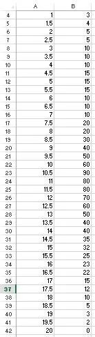
The above is the excel data of speed and time.
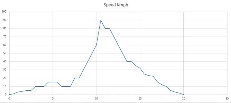
The above graph is created by using the excel data, and it shows the maximum speed 90 at a particular time. we are using the below formulae to calculate the braking power.
Deceleration Power = Mass *1.5*((Vf-Vi)^2)/(2*t*1000)
Force = Mass * Deceleration * Accl. Due to gravity
Deceleration = (Vf - Vi) / Time Taken
Energy = 0.5*m*(Vi - Vf)^2
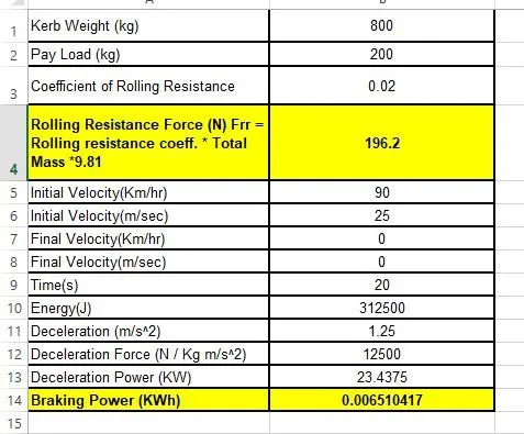
The Braking power is calculated in the excel calculator, and power calculated is for the above graph. The total braking power is 0.00651Kw.
2. Why electric motor can’t develop braking torque at high speed similar to starting? How electric and mechanical brakes are coordinated?
In DC motor operation (separately excited field type), the speed is proportional to the inverse of field magnetic flux but torque is proportional to the flux. The motor speed is controlled by varying the field voltage. Decrease the field volts (thereby flux) to increase the speed but it reduces the torque.
AC motor speed control is done in a different way. The most commonly used motor is AC induction motor. In variable speed applications, inverter is used to control the speed of the motor by varying the frequency applied to the motor. The speed is proportional to the frequency. Until the base speed (nominal speed) the voltage to frequency ratio is kept constant which in turn keeps the air gap magnetic flux constant. The torque is proportional to the flux hence remains constant until the base speed. As power is the product of speed & torque, the power keeps increasing with speed until the base speed. This is called the constant torque mode of operation.
Beyond base speed, the speed is increased by increasing the frequency alone keeping voltage constant. In this mode, the air gap flux decreases with increasing speed. The product of speed & torque remains constant in this operation beyond base speed. This is constant power operation.
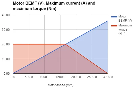
At starting the motor draws a large current due Transient . As torque is proportional to square of current, therefore torque value is also high at this moment.When we applies brakes to motor at that time current value is within the range therfore Torque values is also within the range. From Torque speed characteristic when speed increases torque should decrease to maintain power constant. At the time of starting speed is very low therfore Torque value is very high. At the time of braking, speed value is high therfore torque value will be low. Therfore at the time of braking torque value availabe will be lower. In order to stop the vechicle it requires electrical as well as mechincal brakes.
| Sr. No. | Mechanical Braking | Electrical Braking |
|---|---|---|
| 1. | Mechanical braking produces excessive wear and tear of brake block shoes of brake lining. Therefore, frquent replacement is necessary. | No such need |
| 2. | Due to constant wear and tear of brake lining frquent adjustments are necessary to compensate the offset error, therefore maintanace is costly | Less maintanace |
| 3. | Produce metal dust causing wearing of bearings. | No such a dust is formed |
| 4. | If they are not correctly adjusted the sudden braking action produce shock, this result in discomfort to passengers | Adjustment is easy and braking action is gradual and smooth. |
| 5. | Heat is produce in brake shoes of brake lining, which may damage the lining and may result in failure of braking system. | Heat is produce at a convenient place which is no way harmful to braking system. |
| 6. | No such possibility | 60 to 80 % kinetic energy of apparatus can be fedback to line in regenerative brake. |
| 7. | Mechanical braking alone can be used | Electrical braking is alone not sufficient, it is to be supplement by mechanical braking. |
| 8. | Low cost | High initial cost |
There are two methods to apply this brakes:
1: Series braking
2: Parallel braking
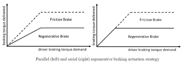
Series braking: In this mechincal and electrical(Regenerative) brakings are applied oneafter the other.
Parallel Braking: In this both Braking methods are applied at a same time. At lower speeds Regenerative brakings are used and at higher speeds mechanical brakes are used.
3. Make a MATLAB program which plots contour of given motor speed, torque and efficiency values. Attach the code as a .m file attach a screenshot of all the plots.
We are creating arrays for the speed and the torque of the motor using the ‘linspace’ command. These arrays are then used to create 2D grid coordinates using the ‘meshgrid’ command. These coordinates will help in the creation of the contour plot. In order to find the efficiency of the motor,
Considerable loss:
Copper losses
Iron losses
Windage losses
Conduction losses
These losses are dependent on the speed and the torque of the motor. Constant of proportionality is 'K'. In each calculation, the speed and the torque are represented as ω and T.
Copper losses = KCu⋅ω2
Iron losses =KFe⋅T2
Windage losses =Kw⋅T3
w= linspace(0,1200);
T= linspace(0,1500);
kc=0.2;
ki=0.009;
kw=0.0002;
[X,Y]=meshgrid(w,T);
copperloss = (Y.^2)*kc;
ironloss = X.*ki;
windingloss = (X.^3)*kw;
constantloss = 21;
outputpower = X.*Y;
inputpower = copperloss+ ironloss + windingloss + constantloss + outputpower;
eff= outputpower./inputpower;
n = linspace(0.7,0.9,10);
box off;
grid off;
contourf(X,Y,eff,n);
xlabel('speed in rad/s');
ylabel('torque in Nm');
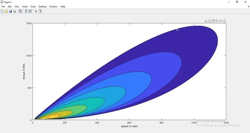
The graph is ploted and thus we can see that the efficiency is near 90% and it is a good efficiency for the motor to be operated. Thus we have ploted the contour of given motor speed, torque and efficiency values and attached the code as .m file.