Week-11 Challenge: Braking
AIM: To defined driving cycle, calculate the energy required for braking.
STUDY 1;
In electric vehicle require ny vehicle for acceleration as well as deacceleration of vehicle aslo. As we require to stop vehicle in stipulated time, we cannot allow vehicle to stop as per its inertia value.,for stopping vehicle we require to apply brake.Braking of vehicle require to deacccelerate vehicle to lower speed within a given time.
Suppose we have UDDS cycle:
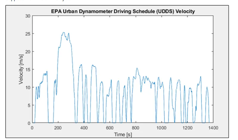
We can observe in this test cycle vehicle needs to stop in given time at some instance also for this we will apply brakes.We will calcilate the power require for braking operation.
This UDDS drive cycle data can be read in the matlab book3.xlsx
https://www.epa.gov/vehicle-and-fuel-emissions-testing/dynamometer-drive-schedules
The EPA Urban Dynamometer Driving Schedule (UDDS) is commonly called the "LA4" or "the city test" and represents city driving conditions. It is used for light duty vehicle testing. The UN/ECE Regulation 53 refers to the EPA UDDS as the "Test Equivalent to the Type 1 Test (verifying emissions after a cold start)."
- To reduce speed from 80 to 40Kmph in 20 sec =292kj
- To reduce speed from 80 to 0 kmph in 10sec =560 kj
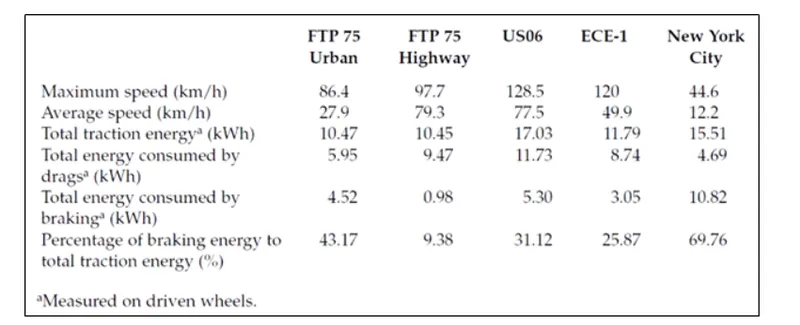
STUDY 2:
- Why electric motor can’t develop braking torque at high speed similar to starting? How electric and mechanical brakes are coordinated?
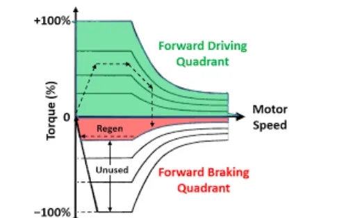
- The torque -speed characteristic of motor is not exact same in the braking and motoring region.
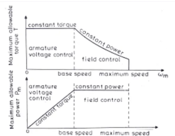
We can say that can achieve 0 to 100kmph speed in 10sec. Acceleration operation goes this way .with low speed and high torque constant torque, a regions is achieved which has acceleration power and by reaching the critical speed it shifts to constant power region, and thus it easy for and EV tp reach 0 to 100.
So Electric motor can't develop breaking torque at a high speed simular to starting because the braking torque of an EV motor is not as high as the acceleration Torque. Therefore Regenerative braking cannot happan so efficiency that we can get all the power back to the battery.
How electric mechanical brake are coordinate?
Electrical and mechanical co-ordination
They are two brake control strategies
1.parallel
2.series
SERIES:
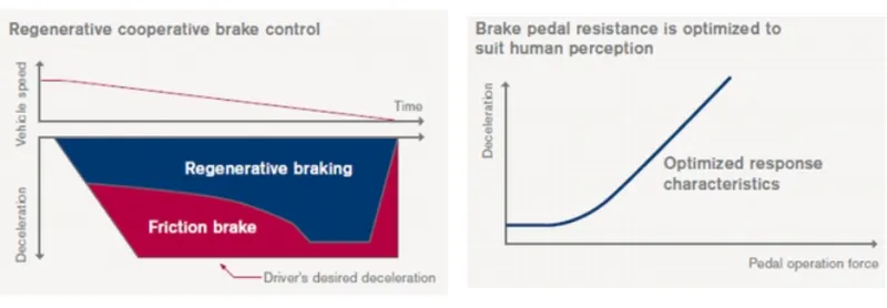
Braking will be applied one after another so they are connected in series, Either one brake strategy at the time either regenerative braking of mechanical braking
PARALLEL:
In the case of parallel both the brakes are applied simultanously both at atime.
ELECTRIC DRIVEN INTELLIGENT BRAKE:
And nissan has developed a practical brake strategy called (EDIB) electric driven intelligent brake developed by nissan leaf
STUDY 3:
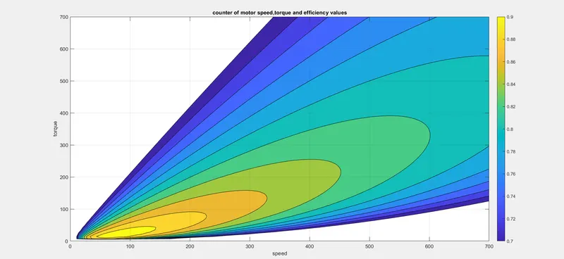
- Make a MATLAB program which plots contour of given motor speed, torque and efficiency values. Attach the code as a .m file attach a screenshot of all the plots.
Matlab program which plots counter of a given motor speed torque and efficiency value.
clc
Wm=linspace(0,700);
T=linspace(0,700);
%losses
Kc=0.2; %copper loss
Ki=0.008; %ironloss
Kw=0.0001;%constant loss
c=20; %constant loss
[X,Y]=meshgrid(Wm,T);
pout=X.*Y;
Kc=(Y.^2)*Kc;
Ki = (X)* Ki;
Kw=((X.^3).*Kw);
pin=pout+Kc+Kw+Ki+c;
efficiency=pout./pin;
effvalues=[0.7,0.72,0.74,0.76,0.78,0.8,0.82,0.84,0.86,0.88,0.9];
box off
grid off
contourf(X,Y,efficiency,effvalues);
colorbar
grid on
The counter-plot for a motor with decreased constant is plotted in defined speed vs torque region based on effciency it can be see that for increasing speed and torque. the efficiency of thenmotor gradually decreases.the level of efficiency is depicated using a colobar.