Week-11 Challenge: Braking
Aim: To study braking system of an electric vehicle.
Objectives:
01.
To calculate the energy required for braking, for given driving cycle.
02.
To study why electric motor can’t develop braking torque at high speed similar to starting? How electric and mechanical brakes are coordinated?
03.
To run MATLAB program which plots contour of given motor speed, torque and efficiency values. Attach the code as a .m file attach a screenshot of all the plots.
Introduction:
What is driving cycle?
A driving cycle is a series of data points representing the speed of a vehicle versus time.
Driving cycles are produced by different countries and organizations to assess the performance of vehicles in various ways, as for instance fuel consumption, electric vehicle autonomy and polluting emissions.
Another use for driving cycles is in vehicle simulations. More specifically, they are used in propulsion system simulations to predict performance of internal combustion engines, transmissions, electric drive systems, batteries, fuel cell systems, and similar components.
Some driving cycles are derived theoretically, as it is preferred in the European union, whereas others are direct measurements of a driving pattern deemed representative.
There are two types of driving cycles:
Transient driving cycles involve many changes, representing the constant speed changes typical of on-road driving.Modal driving cycles involve protracted periods at constant speeds.
The American FTP-75, and the unofficial European Hyzem driving cycles are transient, whereas the Japanese 10-15 mode and JC08 cycles are modal cycles.
What is braking?
Braking is the process of controlling the velocity of an object by inhibiting its motion. An object in motion possesses kinetic energy and to bring the object to a stop this kinetic energy must be removed. Removing the kinetic energy can be accomplished by dissipating the energy to the atmosphere through friction or by converting it into another form of energy. The most common type of braking is a mechanical brake which inhibits motion through friction brake pads. A mechanical brake applies a friction force to convert the kinetic energy of the vehicle into thermal energy which then dissipates into the atmosphere. Braking systems which don't use friction are referred to as regenerative braking systems (RBSs). In RBSs, the kinetic energy is converted into other forms of useful energy, which can be stored for later use, increasing fuel efficiency.
As with any system, the process of braking must follow the principal of conservation of energy. Energy cannot be created or destroyed but only converted from one form to another,
`Eke=Ethermal`
The energy present in an object in motion is given by the following equation:
`Eke=frac{1}{2}*mv^2`
where,
m is the mass of the object in kilograms (kg).
v is the velocity of an object in meter per second (m/s).
Eke is the kinetic energy in joules (j).
From this equation, and assuming the mass of the object is constant, it is clear the in order to remove the kinetic energy from the system, the velocity must be brought to zero.
Friction Braking:
Friction braking is the most commonly used braking method in modern vehicles. It involves the conversion of kinetic energy to thermal energy by applying friction to the moving parts of a system. The friction force resists motion and in turn generates heat, eventually bringing the velocity to zero. The energy taken from the system is given by the following equation:
`Ethermal=Ff*d`
where,
Ff is the force of friction in newtons (N).
d is the stopping distance in meters (m).
Ethermal is the thermal energy produced by the brakes in Joules.
Applying conservation of energy to the above two equations, the thermal energy produced must equal the kinetic energy dissipated:
`Eke=Ethermal`
`frac{mv^2}{2}=Ff*d`
`Ff=frac{mv^2}{2d}`
From this equation it can be seen that increasing the velocity or mass of an object means the applied friction force must be increased to bring the object to a stop in the same distance.
What is braking torque?
Brake torque is essentially the power of the braking system. The brake caliper acts on the disc at a certain distance from the hub center, known as the effective radius. The force exerted by the caliper, multiplied by the effective radius of the system equals the brake torque.
Mechanical Braking:
The most common method of braking in motor vehicles is mechanical or friction braking. In this method, some or all of the vehicles wheels are fitted with brake pads which apply a friction force that inhibits the motion of the wheels. Frictional braking results in a conversion of the kinetic energy gained from fuel consumption to thermal energy. This thermal energy then dissipates to the atmosphere in the form of waste heat.
Large friction forces can be needed to inhibit a vehicle's motion, particularly in large machines and trucks which have a high mass and therefore high kinetic energy. The brake pads, which are responsible for applying the friction force, experience wear over the course of their life due to this friction force. The brake pad wear causes the brakes to become less effective over the course of their life and need regular replacement.
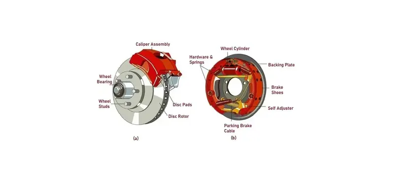
Fig01: Mechanical Brakes.
Regenerative Braking:
Regenerative Braking Systems (RBSs) are a type of kinetic energy recovery system that transfers the kinetic energy of an object in motion into potential or stored energy to slow the vehicle down, and as a result increases fuel efficiency. These systems are also called kinetic energy recovery systems. There are multiple methods of energy conversion in RBSs including spring, flywheel, electromagnetic and hydraulic. More recently, an electromagnetic-flywheel hybrid RBS has emerged as well. Each type of RBS utilizes a different energy conversion or storage method, giving varying efficiency and applications for each type.
RBSs are installed along the drive train or fitted to the drive wheels of a vehicle where they inhibit the motion of the wheels using magnetic fields or mechanical torque. These methods of motion inhibition allow energy to be generated under braking, as opposed to friction brakes which simply waste away energy to slow the vehicle by turning the kinetic energy into thermal energy. Due to the maximum charging rate of the energy storage mechanisms, the braking force from a RBS is limited. Therefore, a traditional friction brake system is required to maintain the safe operation of a vehicle when heavy braking is necessary. RBS can improve fuel consumption and reduce the overall braking load taken on by the vehicles friction brakes, reducing the wear on the brake pads.
RBSs are used in almost every electric vehicles and hybrid electric vehicles. In addition, public transportation such as buses and bullet trains make use of RBSs to decrease the environmental impacts of the transportation fleet and save money.
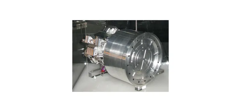
Fig02: Regenerative Brakes.
What is Contour?
A map or plan representing a three-dimensional picture of the ground with the help of the contour line is called a contour map or plan.
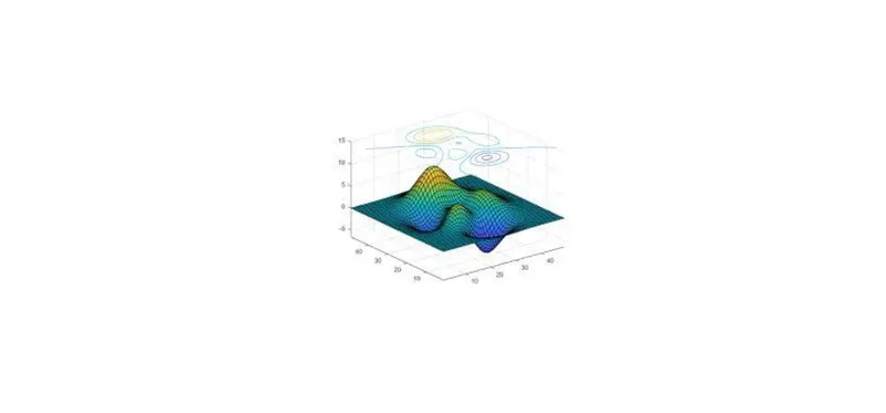
Fig03: Contour plot.
Contour gradient:
A line lying on the ground which maintains a constant inclination to the horizontal is known as contour gradient. It is found out by the instrument clinometer.
Characteristics of the contour lines:
01.
All the points on a contour line have a similar elevation.
02.
Two contour lines never intersect each other because each contour line represents it's own elevation. But in case of overhanging cliff, contour lines cross each other.
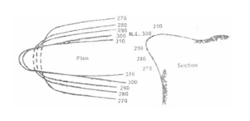
Fig04: Contour for overhanging cliff.
03.
Spacing between contour lines indicates the nature of the ground:
Closely spaced - Steep slopeWide apart - Gentle or flat slopeEqually spaced - Uniform slope
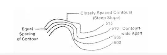
Fig05: Nature of grounds.
04.
For undulating ground or broken surface, the contours are irregular, whereas foe a plane surface they are straight, parallel and uniformly spaced.
Problem Statement:
01.
For a defined driving cycle, calculate the energy required for braking.
02.
Why electric motor can’t develop braking torque at high speed similar to starting? How electric and mechanical brakes are coordinated?
03.
Make a MATLAB program which plots contour of given motor speed, torque and efficiency values. Attach the code as a .m file attach a screenshot of all the plots.
Solution:
01.
For a defined driving cycle, calculate the energy required for braking.
The Time vs. Velocity graph for the given driving cyle is as shown below:
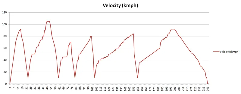
Fig06: Time vs. Velocity graph of the driving cycle.
From observation it's clear that we are performing braking operation for six times throughout the driving cycle.
Therefore to calculate the braking energy required for the given driving cycle we will have to sum up the braking energy of each braking operation of the driving cycle.
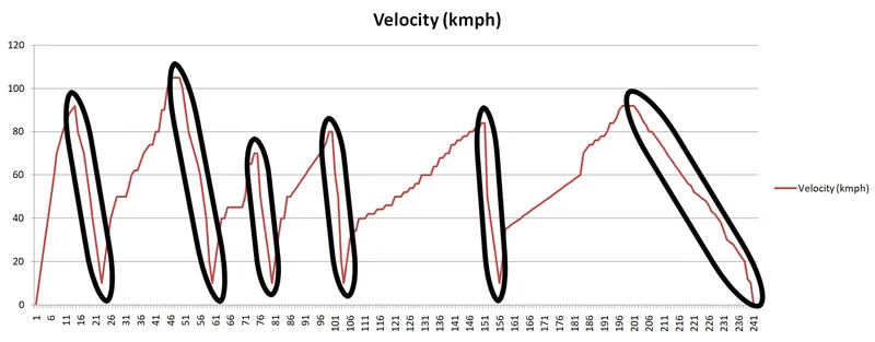
Fig07: Braking operations throughout the driving cycle.
There are two types of energies that are involved in a moving car:
Linear and rotational kinetic energy,
Linear Kinetic energy equation:
`KEl=frac{1}{2}*m*V^2`
Rotational Kinetic energy equation:
`KEr=frac{1}{2}*I*omega^2`
The deceleration from V1 to V2 will reduce the energy. This energy is being saved in hybrid and electrical cars as regenerative energy.
The linear energy change is equal to:
`KEl=frac{1}{2}*m*(V2^2-V1^2)`
And rotational energy change is equal to:
`KEr=frac{1}{2}*I*(omega2^2-omega1^2)`
And
`V=romega=frac{d}{2}*omega`
Therefore,
`omega=frac{V}{r}`
with r being the radius of the wheel,
`r = frac{d}{2}`
However, because of small "I" of the wheels compared to the mass of the car, the contribution of the wheel's change of energy is not significant.
From the study of driving cycle we have the following data:
Braking Operation |
Braking Time |
Initial Velocity |
Final Velocity |
1 |
9 |
92 |
10 |
2 |
11 |
105 |
10 |
3 |
5 |
74 |
10 |
4 |
4 |
80 |
10 |
5 |
5 |
84 |
10 |
6 |
42 |
92 |
0 |
Now we will calculate the braking energy required for each braking operation using the excel sheet calculator as shown below:
Excel sheet Cal: Braking Energy.
Note: Here we will focus on only calculations related braking energy and braking power.
Now we will calculate braking energy of the entire driving cycle which is nothing but sum of all six braking energies:
Braking Operation |
Braking Time (s) |
Initial Velocity (m/s) |
Final Velocity (m/s) |
Braking Energy (J) |
Braking Power (KW) |
1 |
9 |
92 |
10 |
274374 |
30.48 |
2 |
11 |
105 |
10 |
358343 |
32.58 |
3 |
5 |
74 |
10 |
176369 |
35.27 |
4 |
4 |
80 |
10 |
206550 |
51.64 |
5 |
5 |
84 |
10 |
226059 |
45.21 |
6 |
42 |
92 |
0 |
277658 |
6.61 |
Total braking energy: 15.19*10^5 Joules
Total braking power: 201.79 KW
02.
Why electric motor can’t develop braking torque at high speed similar to starting?
Electric motors cannot produce braking torque at high speed similar to starting because once the electric supply is pulled off from the motor during braking the motor, it acts as a generator and due to the flux weakening effect of generator, the generator produces low torque.
Staring operation is carried out at lower speed of the motor whereas the braking operation begins at some specified speed of the motor due to which it becomes difficult for a generator to cope up with both the requirements of the speed and torque.
How electric and mechanical brakes are coordinated?
In an electric vehicle, the total brake distribution is in two aspects: Electrical brakes also called as Regenerative brakes and Mechanical brakes also called as air brake or hydraulic brakes.
Brake force distribution must be uniform. If the regenerative power requirement is more than the charging limit of the battery or more than the regenerative capacity of the machine we must apply mechanical brakes as well. In practical application the combination of these two is applied. So usually it is a combine response of Mechanical brake and Regenerative brake. The techniques used for combining these braking forces are called as Brake Control Strategies.
There are two brake control strategies Series and Parallel. In case od series, we apply Mechanical brakes and Regenerative brake one after other. We can apply only one brake at a time. Whereas in case of parallel we can apply both Mechanical and Regenerative brakes simultaneously. This particular strategy implies both mechanical and regenerative brakes at a time.
In modern cars Electric Driven Intelligent Brakes (EDIB), combination of both electric brakes and mechanical brakes is implemented. It's a parallel braking technique. The control criteria is such that at lower speeds it uses regenerative brakes whereas at higher speed or during initial braking period it uses combination of both electric and mechanical brakes.
03.
Make a MATLAB program which plots contour of given motor speed, torque and efficiency values. Attach the code as a .m file attach a screenshot of all the plots.
The motor has various types of losses happening inside. These are:
Copper losses:
I^2R, where R is the armature resistance and we say that torque is praportional to current, this copper loss can be considered. Whereas to take care of resistance of brushes and also take care of flux and it's effects.
Copper losses `= kc*T^2`
Iron losses:
Iron losses are nothing but Magnetic losses, where the factor is based on the magnetic field effect. Permanent magnets have a constant magnetic field and these iron losses are going to change acoording to the speed of the motor. At various speeds we get various values of the back EMF and that is going to affect the iron losses.
Iron losses `= ki*omega`
Windage losses:
These are mechanical or frictional losses due to windage. These are based on size and shape of the motor.
Windage losses `= kw*omega^3`
Constant losses:
These are denoted by C.
Total losses = Sum of all the losses.
Total losses `= kc*T^2+ki*omega+kw*omega^3+C`
All the motors are model as per the above equations of losses.
Matlab Program: Program file for contour plot of electric motor.
clear all
close all
clc
% Matlab program for pplotting efficiency contours for electric motors.
% The X-axis corresponds to the motor speed w and Y-axis to the torque T.
% Setting up arrays fpr range.

% speed in rad/sec.
x = linspace(0,1000);
% torque in N.m.
y = linspace(0,250);

% Allocating motor loss constants.
kc = 0.2; % for copper losses.
ki = 0.008 % for iron losses.
kw = 0.00001; % for windage losses.
ConL = 20 % for constant motor losses.

% Now make mesh.
[X,Y] = meshgrid(x,y);
Outputpower = (X.*Y); % Power = Speed * Torque
B = (Y.^2)*kc; % Copper losses
C = X.*ki; % Iron losses
D = (X.^3)*kw; % windage losses
Inputpower = Outputpower + B + C + D + ConL;
Z = Outputpower./Inputpower;
% Setting efficiencies for the contour plot.
V = [0.71,0.82,0.87,0.92,0.93,0.97,0.95];
box off
grid off
contour(X,Y,Z,V);
xlabel('Speed/rad.s^-1'), ylabel('Torque/N.m');
hold on
% Now plot a contour of a power output.
% We will draw contours at 8 and 10 KW.
V = [8000,10000];
contour(X,Y,Outputpower,V);
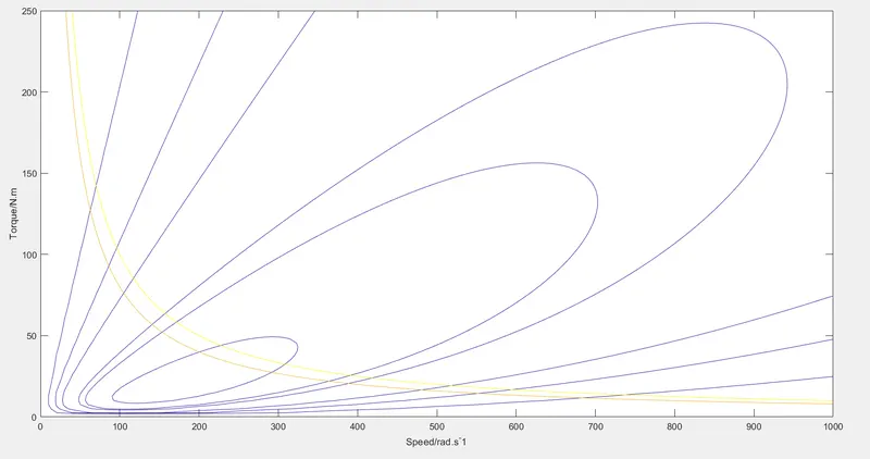
Fig08: Contour plot for the speed, torque and efficiency of the electric motor.
Conclusion:
Here in this study wee learnt the concept of braking energy consumed by the electric vehicle during it's run. Also we learnt the real world apllication and coordination of mechanical and electric brakes. Finally we plot the speed, torque and efficiency contour plot for the electric motor with the help of matlab.