Week-11 Challenge: Braking
CALCULATING BRAKING ENERGY REQUIREMENTS FOR A GIVEN DRIVING CYCLE:
A driving cycle is a series of data points representing the speed of the vehicle vs time. Driving cycles are produced by different countries and organizations to asses the performance of vehice in various ways.
In this calculation, UDDS drive cycle data is used. The total braking energy required for the UDDS drive cycle is calculated.
UDDS DRIVE CYCLE:
The EPA urban dynamometer driving schedule is commonly called the “LA4” or the city test and represent the city driving conditions. It is used for light duty vehicle testing. The UN/ECE regulation 53 refers to the EPA UDDS as the “test equivalent to the type1 test.

The kinetic energy E of the vehicle is given by the formula,
`E = 1/2 mv^2
Where m is the vehicle mass and v is the speed at the start of braking.
If the vehicle speed decreases from initial velocity Vi to the final velocity Vf then the required braking energy is given by
`Braking energy required= 1/2 m(〖vi〗^2-〖vf〗^2)`
Using the formula, whenever deceleration occurs in the drive cycle the decrease in velocity, deceleration value, brake energy is calculated.
MATLAB CODE:
mass = 1000;

time = Drivecycle (:,1);

vel = Drivecycle(:,2);

for i =1:(length(Drivecycle)-1)

if vel(i) > vel(i+1)

E(i) = 0.5* mass * (vel(i)-vel(i+1))^2;

end

end

fprintf('Total braking energy is %d', sum(E))

fprintf('nAverage braking energy is %d', mean(E))

figure(1)

subplot(2,1,1)

plot(Time, vel, 'linewidth', 3,'color','r')

xlabel('Time(sec)')

ylabel('Velocity(m/s)')

title ('Drivecycle')

hold on

subplot(2,1,2)

plot(E, 'linewidth', 3, 'color','g')

xlabel('Time(s)')

ylabel('Energy(J)')

title('Braking Energy')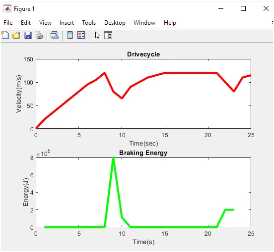
The above fig plot windows refers Drive cycle and thus the energy and velocity is calculated.
2. Why electric motor can’t develop braking torque at high speed similar to starting? How electric and mechanical brakes are coordinated?
Electric motor can’t develop braking torque at high speed similar to the starting, because braking torque is applied in the opposite direction of the rotation. We can use either mechanical brake or electrical brake.
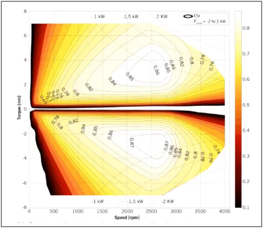
At the time of accelerating vehicle at starting, the maximum torque available motor is operating at constant torque region, in that motor will have maximum torque available, but as motor starts deacclerating motor char are shifted towards braking region. In this we don’t have max torque availablr for braking as motor is already running at higher speed.
Due to this operation, electric motor can’t develop braking torque at high speed similar to starting.
ELECTRICAL AND MECHANICAL BRAKING SYSTEMS CO-ORDINATION:
The electrical and the mechanical systems can be coordinated using braking system strategy subsystem.
- Serial Braking strategy
- Parallel Braking strategy.
The electric motor must be controlled to produce the proper amount of braking force to recover as much braking energy as possible and at the same time the total braking force must be sufficient to meet the vehicle declaration commanded by the driver.
Series Brake Control: The mechanical brake and the electric brake is done one after the another.
Parallel Brake Control: Both the brakes are applied simultaneously. We need both electrical and mechanical braking systems. In emergency braking or parking braking, we need mechanical braking.
Mechanical Brake: In mechanical braking the friction brakes are used in the vehicles to slow down the vehicle. The most common brake types are drum brake and disc brake.
Electrical Brake: It is used to reduce the speed of the motor depending upon the flux and torque. This kind of braking can be done in different methods.
- Plugging type braking
- Dynamic braking
- Regenerative braking.
3.
clear all
close all
clc;
Torque = linspace(1,250,250);
speed = linspace(1,1000,250);
[w,T] = meshgrid (speed,Torque);
Kc = 0.3;
Ki =0.009;
Kw = 0.00005;
C = 30;
Pout = w.*T;
C_loss = Kc*(T.^2);
I_loss = Ki*w;
W_loss = Kw*(w.^3);
Pin = Pout+ C_loss+I_loss+W_loss+C;
Eff = Pout./Pin;
contour(speed,Torque,Eff)
title('Torque speed efficiency contour of the induction motor');
xlabel ('RPM')
ylabel('Torque(N-m)');
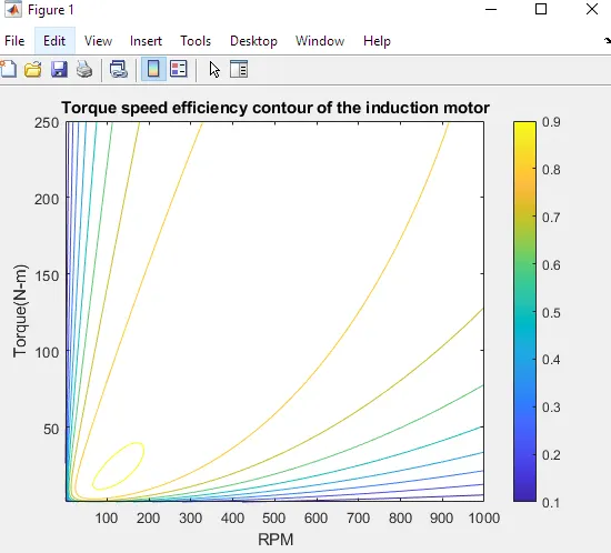
From the contour, we can see that the efficiency is maximum at lower speeds and low torque.
For better efficiency the motor has to operate in the yellow and orange contour region.