Week-11 Challenge: Braking
1) For a defined driving cycle, calculate the energy required for braking.
LINK : https://drive.google.com/file/d/1uWxvGcTXjRbQCJKSHJDiU6jClkkKGYlD/view?usp=sharing
- The drive cycle is generated in a Excel sheet.
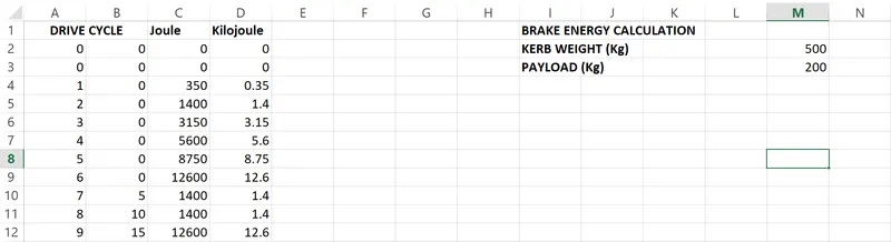
- At each point the kinetic energy calculated is = 1/2*m*v^2. where m is the mass(kerb weight + payload) and v is the velocity (initial velocity - final velocity)
2) Why electric motor can’t develop braking torque at high speed similar to starting? How electric and mechanical brakes are coordinated?
BRAKING :
- The term braking comes from the term brake. we know that brake is equipment to reduce the speed of any moving or rotating equipment like vehicles, locomotives.
- The process of applying brakes can be termed braking. They are classified into two types of braking they are Mechanical braking and electrical braking.
MECHANICAL BRAKING :
- Mechanical brakes all act by generating fricitional forces as two surfaces rub against each other. The stopping power or capacity of a brake depends largely on the surface area of frictional surfaces as well as on the actuation force applied. The fricition and wear encountered by the working surfaces are severe.
- The durability of a brake or service life between maintenance depends heavily on the type of material used to line the shoe or pad.
- Mechanical brakes are assemblies consisting of mechanical elements for the slowing or stopping of shafts in equipment drives. They use levers or linkages to transmit force from one point to another. Braking slows or stops the movement of the coupled shafts.
- There are several types of mechanical brakes. Band brakes are the simplest brake they have a metal band lined with heat and wear resistant friction material. Drum brakes which are commonly used on automobile vehicles in rear wheels work when shoes press against a spinning surface called a drum.
- Disc brakes are constructed of brake pads a caliper abd a rotor. During operation the brake pads are squeezed against with rotor. Cone brakes are made up with a cup and a cone, which is lined with heat and wear resistant material. During actuation the cone is pressed against the mating cup surface.
ELECTRIC BRAKING :
- Electric brakes are devices that use an electrical current or magnetic actuating force to slow or stop the motion of a rotating component. They are used in industrial and vehicular braking applications that require fast response times abd precise tension control.
- The magnet in the backing plate has 2 conductor wires which tap directly into the wiring. When the electricity is on, it magnetices the brake magnet. The magnet is attracted to the drum face. When it contacts this area the friction causes it to rotate which moves the actuating arm and pushes the shoes out against the drum.
- Those shoes have a special brake pad material on them that resists the heat caused by the friction When the shoes press against the inside of the drum they prevent the hub, consequently the wheel that is touching the ground from spinning.
REGENERATIVE BRAKING :
- The concept of regenerative braking can be implemented in conventional vehicles using flywheels. Flywheels are disks with high inertia that rotate at a very high speed. They act as a mechical energy storage device by taking up the kinetic energy of the vehicle during braking.
- The energy recovered during the braking process can be used to assist the vehicle during starting or up hill movement.
- In the mechanical braking system a reverse torque is exerted on the wheel when we press the brake pedal. Similarly in the regenerative braking mode the speed of the vehicle is reduced by initiating a negative torque in the motor with the help of the motor controller.
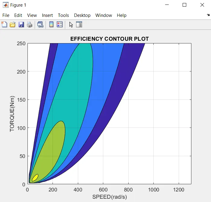
3) Make a MATLAB program which plots contour of given motor speed, torque and efficiency values. Attach the code as a .m file attach a screenshot of all the plots.
LINK : https://drive.google.com/file/d/1itouut3f0wKI65lil6aTtgt2d_LCqP1p/view?usp=sharing
clear all
close all
clc

%for contour plot
s = linspace(0,1300);
t = linspace(0,250);

%copper loss
kc = 0.3;

%iron loss
ki = 0.08;

%winding loss
kw = 0.0001;

%constant
c = 5;

[x,y] = meshgrid(s,t);

%power = speed*torque
output_power = (x.*y);

%copper loss = kc*torque^2
cu = kc.*(y.^2);

%Iron loss = speed*ki
i = ki.*x;

%windage loss
w = kw.*(x.^3);

%input power = output power + losses
input_power = output_power + cu + i + w +c;

%efficiency
z = output_power./input_power;

%mapping of efficiency
v = [0.70, 0.75, 0.80, 0.84, 0.90,0.95];
contourf(x,y,z,v)
grid on;
title('EFFICIENCY CONTOUR PLOT')
xlabel('SPEED(rad/s)');
ylabel('TORQUE(Nm)');
EXPLANATION OF THE CODE :
- First the limits of the plots have been given using the linspace command.
- The inputs copper loss, iron loss, winding loss and the constant loss have been given as the inputs.
- Generating the mesh grid. Calculating the output power, copper loss, iron loss, winding loss, input power and calculating the efficiency.
- The values for mapping the efficiency point. The command for contour plot is given.
- Label command is used to label and title command is used to give title for the plot.
EQUATION USED :
- Power = speed * torque
- Copper loss cu = Kc.T^2
- Iron loss I = ki.W
- Winding loss W = kw.W^3
- Constant loss is given as C
Where,
W = speed(rad/s).
T = torque(Nm).
kc = copper loss constant.
ki = iron loss constant.
kw = winding loss constant.
OUTPUT :