Week-11 Challenge: Braking
Question 1:
Solution:
Before going into the MATLAB program, let us get a brief idea of Braking and the corresponding Braking Energy.
Braking is basically a process of controlling the velocity of a moving object by resisting its motion. A vehicle in motion posseses a good amount of Kinetic Energy and so in order to deaccelerate its motion the kinetic energy must be reduced and which can be accomplished by dissipating the energy to the atmosphere in the form of friction or by converting it to other form of energy. The most common types of braking is the Mechanical Brake which deaccelerates the vehicle motion through friction brake pads. Another form of braking which is now of widely used in EV or HEV type of vehicles is the Regenerative Braking where the Braking Energy is used to charge the Battery thereby increasing the efficiency of the Vehicle. It happens in a fashion that when the vehicle starts to deaccelerate by taking the foot off the throttle, the electric motor stops supplying power so the vehicle will slow down and when the motor stops it get immedeately disengages and then starts running backwards and in this situation the Motor will starts running as a Generator which then captures the Kinetic energy of the wheel and converts it into electricity and then get ultimately stored in the Battery.
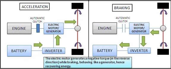
Basically in today's scenario both Regenartive and Mechaniacl Braking is equally important.
In the Matlab Program, our intention is to find out the Braking phenomena whenever the Vehicle deaccelerates and to find out the Total Braking Energy usage during that condition. For that purpose, the driving cycle choosen is as follows:
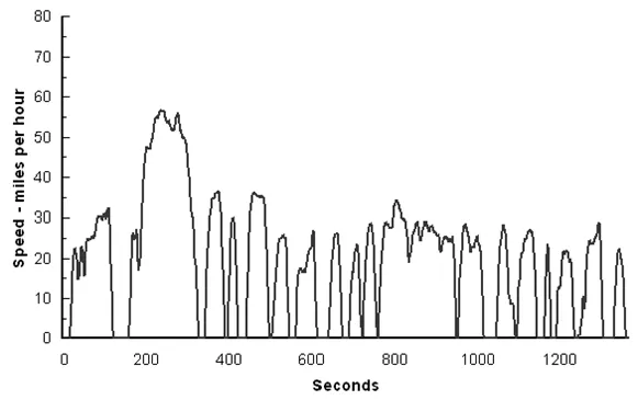
This driving cycle consists of 1373 data points and each of these points are used to compute the Braking Energy in a loop fashion. These data points in the excel format are shown as follows:
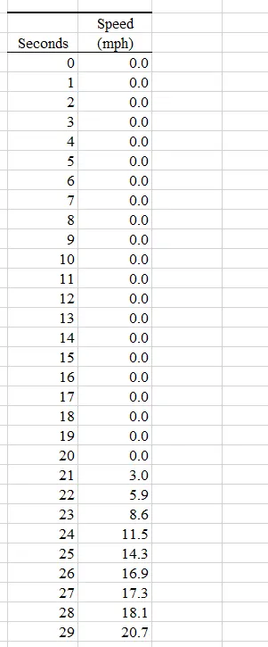
This excel file is then loaded in the Matlab as follows:

This points are used to compute the Braking phenomena at every deacceleration condition of the vehicle and also to find out the Total Braking Energy through the MATLAB program which is shown as follows:
Time = City_Drive_Cycle(:,1);
Speed = City_Drive_Cycle(:,2);
Mass = 900;
S_initial=[];
S_final=[];
for i=1:(length(Speed)-1)
    if Speed(i)>Speed(i+1)
        B_E(i) = 0.5*Mass*(Speed(i)-Speed(i+1))^2; %Computing the Value of Binding Energy at every step
    end
end
fprintf('Total Braking Energy in kWh = %d',sum(B_E));

%Plotting all the given results as follows:
figure(1)
subplot(2,1,1)
plot(Time,Speed,'linewidth',2,'color','r')
xlabel('Time(sec')
ylabel('Speed(kmph)')
grid on
title('City Drive Cycle')

subplot(2,1,2)
plot(B_E,'linewidth',2,'color','b')
xlabel('Time(sec)')
ylabel('Braking Energy(kWh)')
grid on
The corresponding Braking phenomena taking place at every deacceleration condition of the Vehicle w.r.to the Driving Cycle is plotted as following:
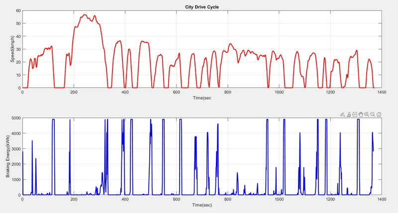
It is very clearly seen from the graph that whenever the vehicle is deaccelerating from higher initial position to a lower final position, the braking phenomena is taking place which is shown in the below plot. Corresponding to this the Total Braking energy used by the Vehicle is coming out as follows:

Question 2:
a)Solution:
For an Electric Motor the Torque-Speed Charateristics along with the Efficiency Contour is come as follows:
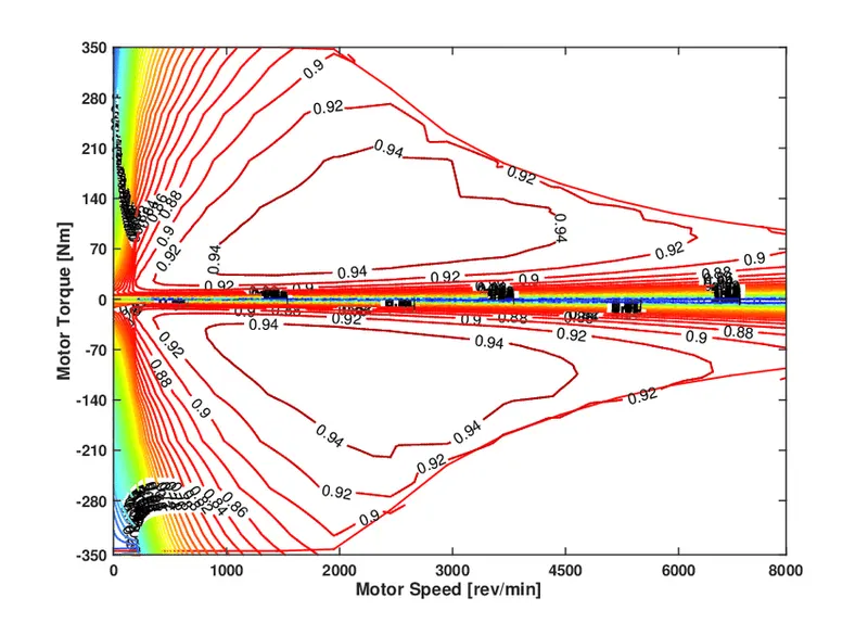
It shows both the 1st and the 2nd quadrant operation which is the Motoring and the Braking respectively. Now according to the question if we operate the Motor at high speed say around 4500RPM in the efficiency region of 0.94 then the Motor initially wil accelerate from the constant torque region to gain the maximum starting torque which is 350Nm and then it will move to the constant power region in order to meet the speed demand. Now at that position if the brakes are applied then the curve will get shift to the 2nd Quadrant and the corresponding Torque that will get generated is around 210-140Nm which is very less compared to the Starting torque. Thus from the Torque-Speed Charateristics it can be easily understand why the electric motor braking torque at high speed is always less than the Starting Torque.
Another way it can be explained in brief is that the torque of the motor is inversely proportional to the square of the Speed. So at high speed the braking torque generated will always be less than the torque produced at the time of starting i.e when the speed is low.
b)Solution:
The Co-ordination of the two types of brakes is done on the basis of how much energy capture is required. With some the drive can decide how much Electrical braking to use, usually by moving the gear shift lever while slowing down. This condition is also known as "One-Pedal Driving" where the driver may be able to get through heavy traffic by only using the throttle, accelerating enough to move ahead as needed and then letting off the pedal and letting the Electrical braking making the stop. But an Electrical Braking system isn't enough to stop the vehicle at every situation especially when driving at a higher speed and due to this reason EV or HEV vehicle also has conventional hydraulic brakes. And because of this two type of scenario both EV and HEV types of vehicle comes up with two types of control strategy which are as follows:
- Series Brake Control: Here both the Mechanical as well as the Electrical in the form of Regenerative Braking is done but one after the other.
- Parallal Brake Control: In this situation both the Mechnical as well as the Regenrative Brakes are applied simultaneously.
These two situation is shown in the following diagram:
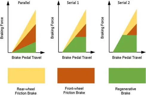
Here the Mechanical brakes are always applied during the Emergency situation and also during the parking of the vehicle. Whereas the Electric Brakes are applied for efficient and smooth operation and also allows the driver to recover the lost energy.
Types of Electrical Brakes are as follows:
- Plugging: In this situation the three phase voltage teriminals at the stator terminals of the Induction Motor is reversed.
- Dynamic Resistor Braking: Here in the variable frequency drive systems, when the Motor is braking and acting as an Induction generator it returns back power to the DC link capacitor and the voltage of the DC link increases. A resistor can thus be used to dissipate the excessive charge on the capacitor.
- Regenerative Braking: In this situation the excessive energy is returned back to the Battery by using a special bi-directional Inverter placed in parallal with the uncontrolled rectifier that is used in the variable frequency drive system.
Question 3:
Solution:
The efficiency contour mapping is done by using some equations which are given as follows:
Power=Torque*Speed
Copper Losses=`kundersetc`*`T^2`
Iron Losses=`kunderseti`*`omega`
Friction and Windage Losses=`kundersetw`*`omega^3`
Other Constant Losses denoted as C.
Therefore, Total Losses=Copper Losses+ Iron Losses+ Froction and Windage Losses+ Constant Losses
=`kundersetc`*`T^2`+`kunderseti`*`omega`+`kundersetw`*`omega^3`+C
So, Input Power=Output Power+Total Losses
`:.`, Efficiency(`eta`)=Output Power/Input Power.
Using the above governing equations the MATLAB program for finding the Speed Torque relationship along with the mapping of the Efficiency Contour is given as follows:
x=linspace(1,1000);%Speed in rad/sec
y=linspace(1,250);%Torque in Nm
%Assigning Motor Loss Constants as follows
kc=0.2;%Copper Loss Constant
ki=0.008;%Iron Loss Constant
kw=0.00001;%Windage Loss Constant
conL=50;%Constant Loss
%Now Make mesh
[X,Y]=meshgrid(x,y);
Outputpower=(X.*Y);%Power=Torque*Speed
B=(Y.^2)*kc;%Copper Losses
C=X*ki;%Iron Losses
D=(X.^3)*kw;%Windage Losses
Inputpower=Outputpower+B+C+D+conL;
Z=Outputpower./Inputpower;
%the efficiency for which a contour will be plotted
V=[0.70,0.80,0.85,0.90,0.91,0.92,0.925,0.93];
box off
grid off
contour(X,Y,Z,V);
xlabel('Speed in rad/sec'),ylabel('Torque in Nm');
title('Efficiency Contour Mapping');
hold on
grid on
%V=[8000,10000];
%contour(X,Y,Outputpower,
The corresponding efficiency contour is coming as follows:
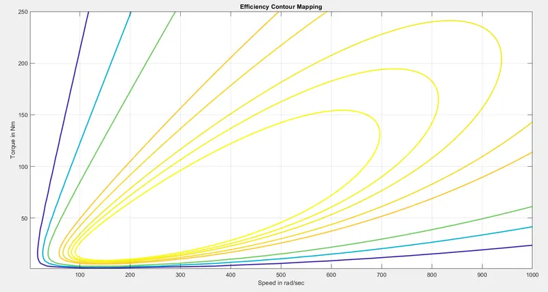
Each of these contours represents efficiency of a particular magnitude which is same over the same contour. It is to be noted that the innermost contour posses the highest efficiency whereas the outermost contour posses the lowest efficiency. Deciding the particular efficiency contour along with the value of the Speed and the Torque , the operating point of the Motor gets decided.