Week-11 Challenge: Braking
Aim:
1.To make a drive cycle for calculating the energy required for braking.
2.To answer the question ‘why electric motor cant develop braking torque at high speed similar to starting? How electric and mechanical brakes are co ordinate?’
3.Make a MATLAB program which plots contour of given motor speed, torque and efficiency values. Attach the code as a .m file attach a screenshot of all plots.
Explanation:
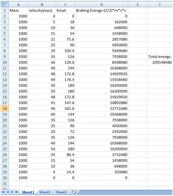
1.To create a driving cycle and find the braking energy we had used the excel sheet to have a driving cycle and find the braking energy values.
Braking energy=(1/2)*m*v^2
Where,
m =Mass(vehicle + load)kg
v =(intial velocity – final velocity) in m/s
To convert the meter/second into kmph we have to multiply value by 3.6 i.e 18/5, because the units has to be same.
2.
(i)We know that torque of the induction motor is in inverse proportional to the square of the rotor speed. So at high speed the torque will be less. That’s why at high speed electric motor cannot produce braking torque similar to starting.
(ii)The electric motor must be controlled to produce the proper amount of braking force to recover as much braking energy as possible and at the same time, the total braking force must be sufficient to meet vehicle deceleration commanded by the driver. For meeting th sufficient braking EV vehicle we use brake control strategies. Series and parallel brake controls in which the mechanical and electrical braking are taking place one after the another in series braking and both are applied at the same time in parallel braking. We need both the types of braking where for the parking and emergency braking the mechanical braking are used.
Mechanical brake is the friction brake that is used to slow down the vehicle. The most common type of brakes are drum brake and disc brake.
In electric braking it is used to reduce the speed of the motor depending upon the flux and torque. This kind of braking can be done in three methods
- Plugging type braking
- Dynamic braking
- Regenerative braking.
3.
Code:
clc
clear all
close all

omega=linspace(0,1500);
T=linspace(0,300);
kc=0.25;
ki=0.0075;
kw=0.0001;

[X,Y]=meshgrid(omega,T)
copper_loss=(Y.^2)*kc;
iron_loss=X.*ki;
windage_loss=(X.^3)*kw;
con=20;
o_p=X.*Y;

input_power=copper_loss+iron_loss+windage_loss+o_p
eff=(o_p)./(input_power);
n=linspace(0.65,0.95,10)
contour(X,Y,eff,n)
xlabel('rpm')
ylabel('troque')
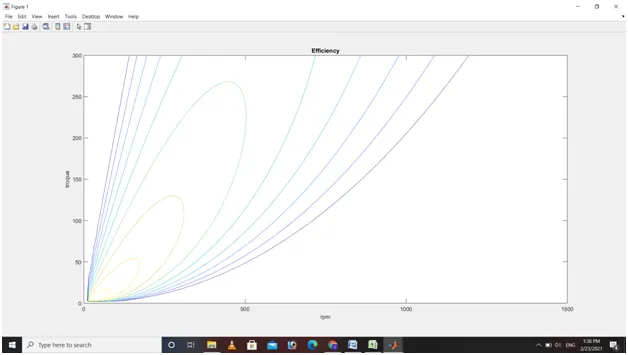
title('Efficiency')- Arrays are formed for rotational speed and torque using linspace command
- In a motor there are four types of losses
- Copper loss(kc)- these are generated as a result of the armature rsistance, T proportional to I =kc*T^2
- Iron loss(ki)- change according to speed, as speeds are changed back emf of different values are generated(magnetic field effect)= ki*w
- Windage losses- due to size and shape of motor =kw*w^3
- 4other losses are in constant (c)
- Ameshgrid is formed with X as rotational speed and Y as torque
- Output power at all these points(x,y) is found by T*W
- Total losses is sum of all above losses
- Input power is sum of output power and input power
- To form a contour different variable calues are assigned for efficiency. Here the V which contains efficiency values are plotted on w-T plane
Output:
Results:
Thus the answers are been given with proper explanations and output.