Week-11 Challenge: Braking
Braking
- For a defined driving cycle, Calculate Energy Required for Braking?
Regenerative Braking:
Moving Vehicles have a lot of kinetic energy, and when brakes are applied to slow a vehicle, all of kinetic energy has to go somewhere, back in the Neanderthal days of internal combustion engine cars, brakes were solely friction based and converted kinetic energy of the vehicle into wasted heat in order to decelerate a car. Regenerative braking uses an electric vehicle’s motor as a generator to convert much of kinetic energy lost when decelerating back in to stored energy in vehicle’s battery. The next time the car accelerates, it uses much of energy previously stored from regenerative breaking system instead of tapping in own energy reserves.
A motion possesses kinetic energy and to bring the object to this kinetic energy must be removed. Removing kinetic energy can be accomplished by dissipating the energy through friction by converting in to another form of energy. The most common type of braking is mechanical brake which inhibits the motion through friction brake pads. A mechanical brake applies a friction force to convert kinetic energy of vehicle in to thermal energy which then dissipates into the atmosphere. As with any system, the process of braking must follow the principal of conservation of energy. Energy can’t be creating or destroyed but only converted from one form another.
The energy present in an object in motion is given by the following equation:
E kinetic = 1/2 *m*v^2
‘m’ is the Mass of Object in (kg)
‘v’ is the Velocity of Object in (m/s)
E kinetic is kinetic energy in (J)
Now all the kinetic energy of vehicle is converted into heat energy (or) Regenerative energy which is fed back in to battery combination of both.
Kinetic Energy of Vehicle = Braking Energy
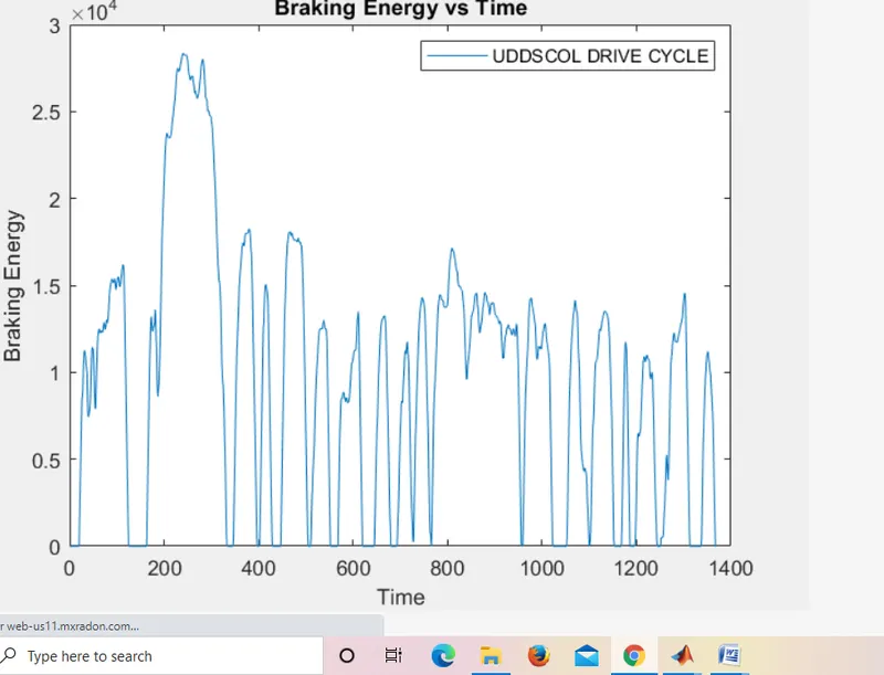
The following code describes the breaking energy required for this drive cycle:

 2. Why electric motor can’t develop torque at high speed similar to starting? How electrical and mechanical brakes are coordinated?
AC or DC there is no torque at maximum speed, gradually the torque decreases at high speed as speed tends to be maximum speed. It doesn’t occur at the beginning of acceleration because most of the torque is used to increase the kinetic energy of the load (and motor). But when the speed is already high and no extra load is applied not possible to increase the torque as well as to develop braking torque. The braking operation happens in the motion which is been distributed as proportion in the brake energy and regenerative braking.
There are two types of braking:
(1) Mechanical braking: Mechanical brakes all act by generating frictional forces as two forces rub against each other. The stopping power or capacity of a brake depends largely on the surface area of frictional surfaces as well as actuation force applied. Mechanical brakes are assembles consisting of mechanical elements for the slowing or stopping of shaft in equipment drives. They use levers or linkages to transmit force from one point to another. Braking slows or stops the movement of the coupled shafts. There are several types of mechanical brakes.
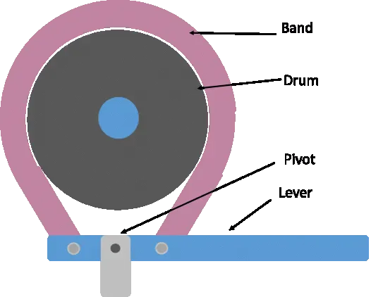
Band brakes: These are simplest brake configuration; have a metal band lined with heat and wear resistant friction material.
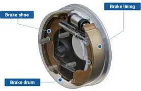
Drum Brakes: These are commonly used o automobile rear wheels, work when shoes press against a spinning surface called a drum.
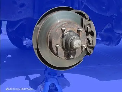
Disc Brakes: These are constructed of brake pads, a capillary, and a rotor. During operation the brake pads are squeezed against the motor.
(2) Electrical Braking: Electric brakes are devices that use an electrical current or magnetic actuating force to slow or stop the motion of rotating component. They are used in industrial and vehicular braking applications that require fast response times and precise tension control. The magnet in the backing plate has 2 conductor wires which tap directly in to wiring. When electricity is on, it magnetizes the brake magnet. The magnet is attracted to the drum face. When it contact this area, the friction causes it to rotate which moves the actuating arm, and pushes the shoes out against the drum. Those shoe have a special brake pad material on them that resists the heat caused by that friction.
A electric braking scheme is called Regenerative Braking is now employed for electric braking. During the braking action, the motor is operated as generator. As we know that during generating action, a counter torque is produced. So this counter torque opposes the motion of motor and motor comes to halt. More over, the brake energy is converted to electrical energy which can be feedback to source using power converters.
Electrical and Mechanical brake condition:
These are mainly 2 ways by which the Electric vehicles could be braked:
Series: Regenerative braking and mechanical breaking both are applied one after another.
Parallel: Regenerative breaking and mechanical breaking both are applied simultaneously.
When the brake pedal is pressed the hydraulic fluid reaches the brake pistons and created the braking pressure o the wheels and the same kinetic energy is been used by Regenerative Braking for generating more power using the Bi-directional motor operates as generator while braking.
- Make a MATLAB program which plots contour of given motor speed, torque and efficiency values. Attach the code as a. m file attach a screenshot of all the plots?
A contour plot is graphical technique for representing a 3-dimensional surface by plotting constant Z slices, called contours, on a 2-dimensional format. That is, given a value for z, lines are drawn for connecting the (x, y) coordinates where that z value occurs.
MATLAB CODE:

Explanation:
In this MATLAB script, we create arrays for the speed and torque of the motor using the ‘line space’ command. For the speed, consider a range of values from 0 to 2000 radians per second where as for the torque, the range of values from 0 to 300NM. These arrays are used to create a 2D grid coordinates using the ‘mesh grid’ command. These coordinates help to creation of the contour plot. In order to find the efficiency of the motor, need to consider losses that occur in motor’s operation. These are
Copper losses
Iron losses
Wind age losses
Conduction losses
These various losses are dependent on the speed and the torque of the motor. The each also have a characteristic constant of proportionality which all assumed for the following calculations and represented as ‘k’ in each calculation, the speed and the torque are represented respectively as : w and T
Copper losses = KCu.w2
Iron losses = KFe.T2
Wind age losses = Kw.T3
The values of coefficients are taken as general values. Conduction losses are assumed to be 18joules.
Finally we plot the contour with the ‘contour’ command. In addition, an array for the efficiency values want to plot for is created called “W” and is assigned for values ranging from an efficiency level of 0.75 to 0.95. This array is used in the creation of the contour. Axis labels and a title is also made for better readability.
OUTPUT:
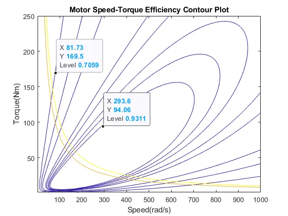
From this, contour plot we can see that the highest level of efficiency arises in the innermost contour plot and this efficiency decreases as the contour increases in size from the innermost contour.