Week 11 Challenge
AIM AND INTRODUCTION :
- To calculate the temperature load for the RC bridge with M40 grade to be constructed in Delhi for the span of 9m and to apply the calculated temperature load on the bridge using staad pro.
- Daily and seasonal fluctuations in shade air temperature, solar radiation, etc cause the following.
- The variation of maximum and minimum temperature due to seasonal changes causes temperature load on the bridge.
- This load causes temperature restraint which causes thermal expansions or contraction at joints, which accelerates material degradation and increases stress in the structure.
- The difference of temperature in the top and bottom surface of the superstructure needs to be applied as load in staad pro for analyzing the structure.
- IS 875 part five deals with temperature load.
- If the bridge is located in the zone of temperature above 20 degrees celsius mean of maximum and minimum temperature + or - 10 degrees whichever is critical is needs to be assumed.
- If the bridge is located in the zone of temperature below 20 degrees celsius + or - 5 degrees whichever is critical needs to be assumed.
- The temperature load is need to be calculated first after that temperature stress and rupture needs to be checked.
- After checking, derive the permissible tensile stress due to temperature load, and apply the temperature load in the structure.
PROCEDURE :
Load calculation :
M40 grade, location- delhi
- Maximum temperature in the location as per IRC 6 Isotherm at the location = 42.5degrees
- Minimum temperature in the location as per IRC 6 Isotherm at the location = 5degrees
- Effective temperature difference = (42.5-5)/2 + 10 = 28.75degrees.
- Stress due to temperature = α * ΔT * E
= (11.27*10^-6) * 28.75 * 5000(40)^0.5
= 10.24 KN/m^2
- Maximum permissible stress = 2/3 * 0.7 * (40)^0.5
= 2.95 KN/m^2
- Hence, the stresses are restricted to 3 KN/m^2.
- Max. temp = 42.5degrees
- Min. temp = 5degrees
- Positive temp. difference
Temp. at top = 42.5degrees
Temp. at bottom = (2.1/17.8) * 42.5 = 5.01degrees.
- This temp. variation is applied as loading in staad pro.
- The step by step procedure for the design of bridge and temperature load input is as follows:
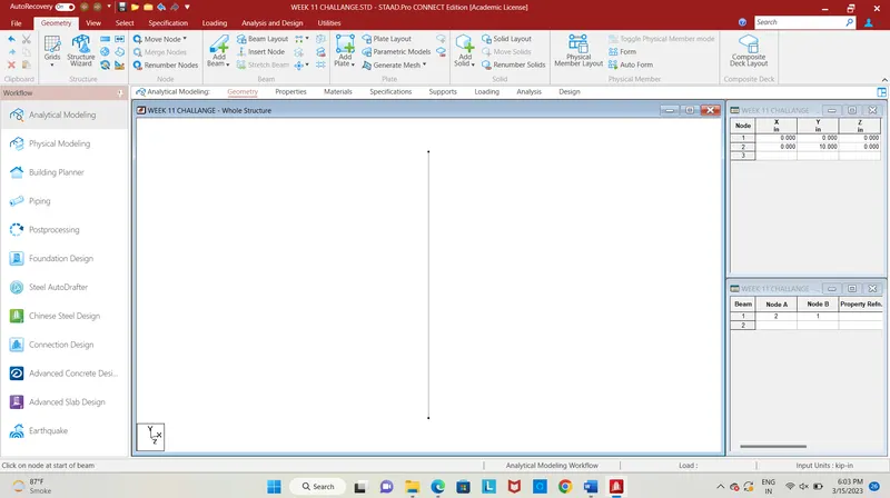
Fig. 1
- First enter the coordinates of nodes for pier, as (0,0,0) and (0,10,0) and connect the nodes by using add beam command.
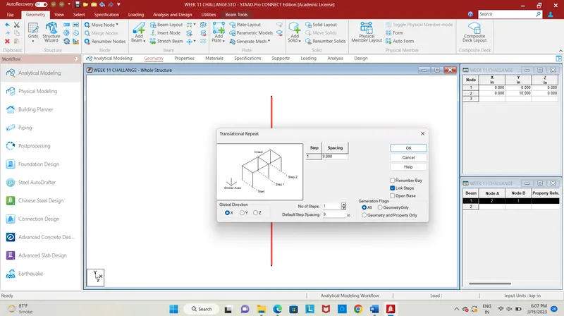
Fig. 2
- Repeat the pier in the x-direction for a step at a spacing of 9m, the 9m indicates the span of the beam.
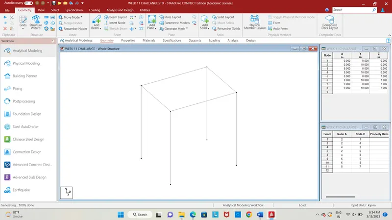
Fig. 3
- Repeat the two piers in z-direction at a spacing of 7m for one step, the 7m shows the width of the deck slab.
- Next step is to provide properties to the beams.
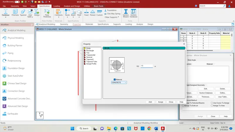
Fig. 5
- Add a circular section of 1.5m of concrete material and select the piers click on assign to selected beams.
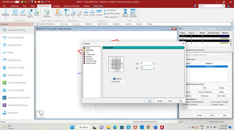
Fig. 6
- Add a rectangular section of size 1.5m*0.9m for main beam and cross beam and select the beam click on assign to selected beams.
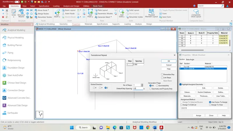
Fig. 7
- The next step is we need to add plates to the deck slab, select the corner node and copy it x-direction at a spacing of 0.5m for one step.
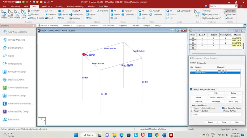
Fig. 8
- Copy the nodes in the z-direction at 0.5m spacing for one step, click on add plate command and select the four nodes to add a plate.
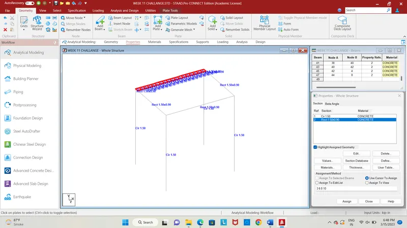
Fig. 9
- Copy the plates in the x-direction at a spacing of 0.5m for 17 steps.
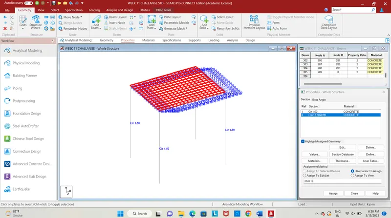
Fig. 10
-
select the plates in the x-direction and repeat them in z-direction for 13 steps at a spacing of 0.5m.
- The plates have been created for the entire deck slab, next, we need to specify the thickness for the deck slab.
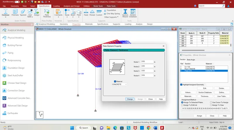
Fig. 11
- Add a plate thickness of 550mm as given, select the plate using plate curser and click on assign to the selected plate to assign the property to the deck slab.
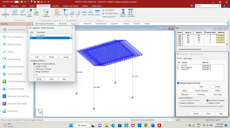
Fig. 12
- Provide fixed support to the bottom nodes of the pier by selecting peir and assign to selected nodes.
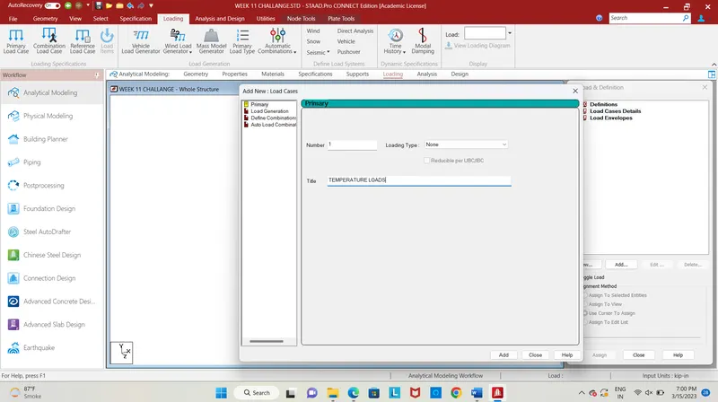
Fig. 13
- The next step is we need to give loading to the structure, add load case details and give title as temperature loads.
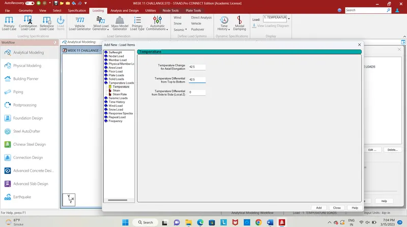
Fig. 14
- Select the temperature load enter the load values as 42.5 for axial elongation, and temp. differential from top to bottom as 42.5
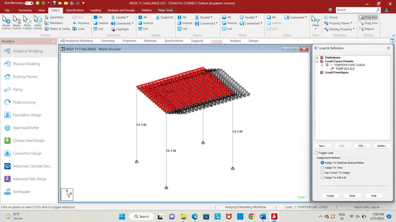
Fig. 15
- Now click on the temperature load, select the plates using the plate cursor and click on assign to selected plates to assign the load to deck slab.
RESULT :
- After assigning the load, click on the run analysis command for the analysis of the designed bridge, after analysis click on go to post-processing mode for further analysis of the structure to check with bending moment, shear force, plate stresses.
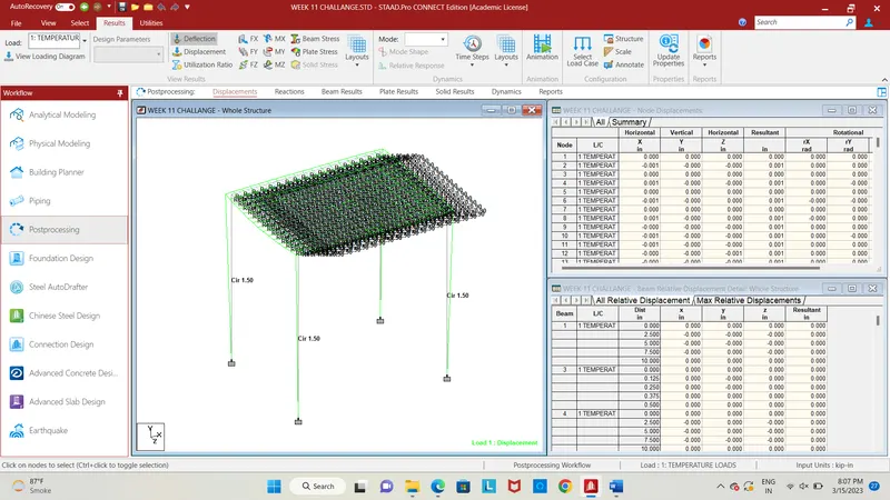
Fig. 16
- The fig. shows the deflection pattern of the bridge structure due to the temperature load.
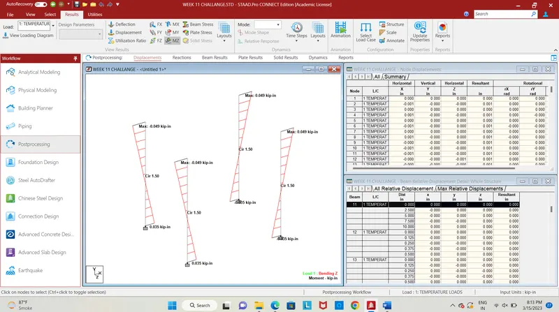
Fig. 17
- Click on Mz the bending moment along z-direction will be shown for the temperature load for the piers with maximum and end values.
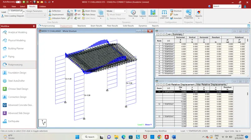
Fig. 18
- In the results, tab select Fy the shear force in y-direction for temperature load, the shear force has shown above.
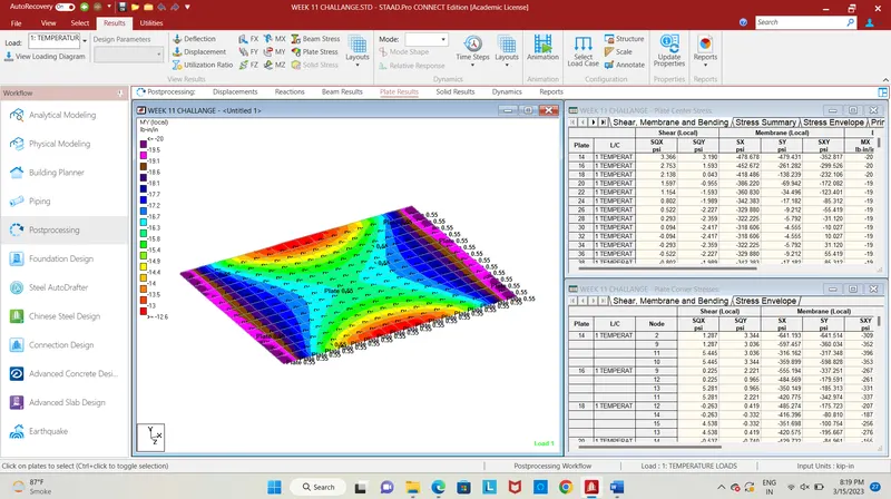
Fig. 19
- Select plate stress and select the stress type as My local the stress will be shown in the contour image.
- Thus the temperature load have been calculated and applied on the designed bridge using staad pro.