Week 11 Challenge
1. Copy T-Intersection civil cell DGNLIB file and place a copy in the project folder.
2. Open the DGNLIB file. List out the names of civil cells present in that DGNLIB.
3. List out the References in the civil cell.
4. On any one civil cell, change the secondary alignment bearing, so that it is skewed by 10ᵒ. Confirm if the civil cell, transitions as per the alignment shift.
5. Design 2 driveways alignment and profiles perpendicular to the INT_01 alignment. Refer to the background imagery.
6. Place appropriate civil cell on one driveway.
7. Design the second driveway by manual method (using geometry, terrain, modeling tools)
8. Generate component quantities of the Corridor_INT_01.
9. Generate cut-fill volumes and Mass Haul diagram and report for INT_01.
10. Generate corridor, legal, input, geometry, earth works XML reports. Save each report in PDF format in the project folder.
1. Copy T-Intersection civil cell DGNLIB file and place a copy in the project folder.
- Open ORD
- Create the new file called civil cell with a 2D seed file,blank page open up
- Now to go model detailing
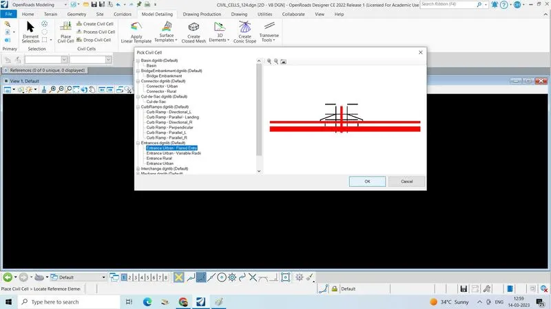
- Click on civil cells tab, click on place civil cells small window opens up
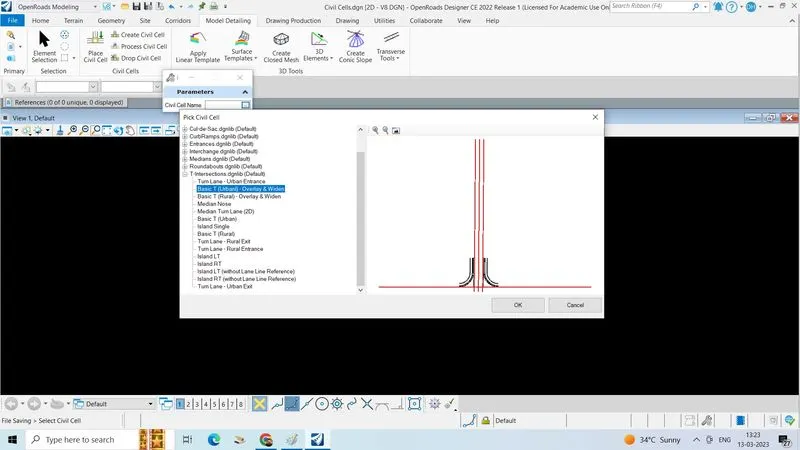
- Click on the 3 dots ... pick civil cells window open ups
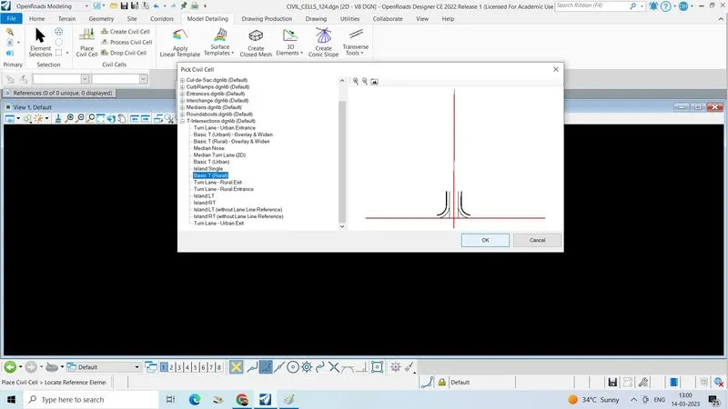
- Click on T-intersection dgnlib(defualt)
- Click on basic T(urban) and the template window open ups
- Note: Reference lines must be designed in the dgn file before placing any civil cells template into any file
- Now goto DGN Library-> For this goto file(top left corner)
- Click on settings
- Click on configuration
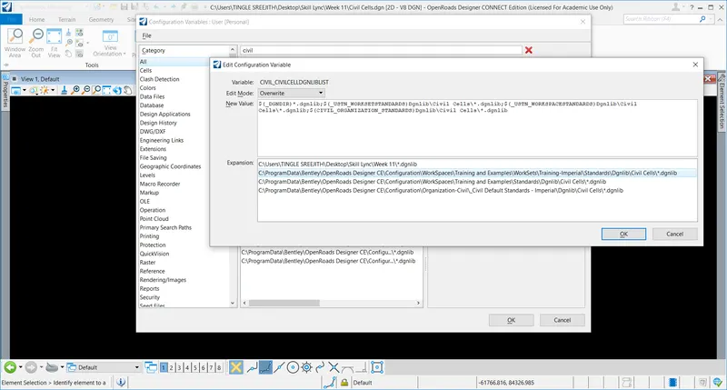
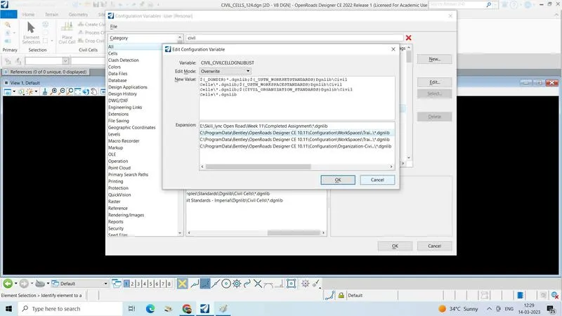
- Click on variable, window open up which shows the path for the civil cells dgn library
- (Copy or snapshot the reference for the furture)
- NOTE: Don't edit directly in the edit configuration variable
-
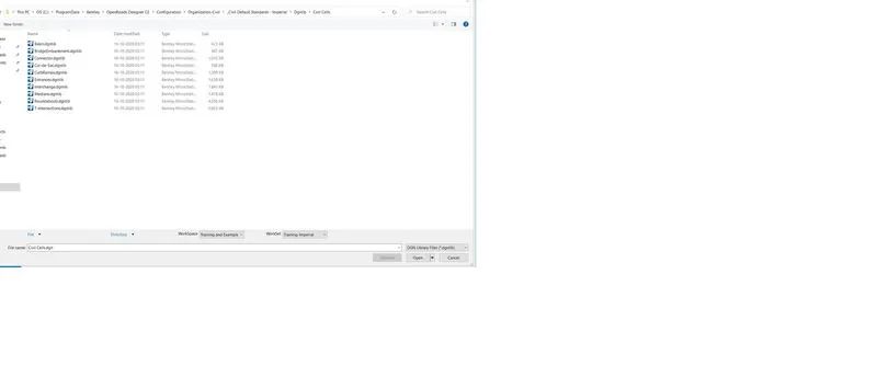
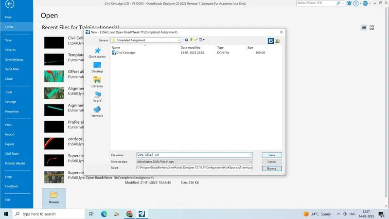
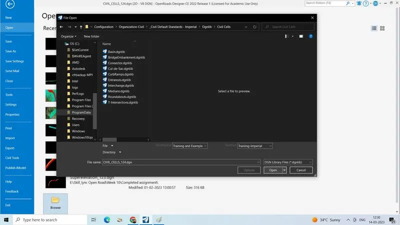
Now close the window and go back to File=>Open=>Browse=>(before browsing the file make changes in the file type as DGN library files) and no files are visible
-
So browse C: program data/Bentley/openroads designer CE/configuration/Organization -Civil/Imperial/Dgnlib/civil cells
-
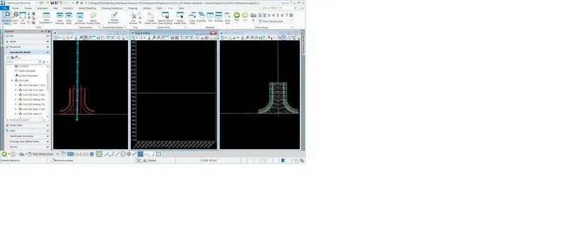
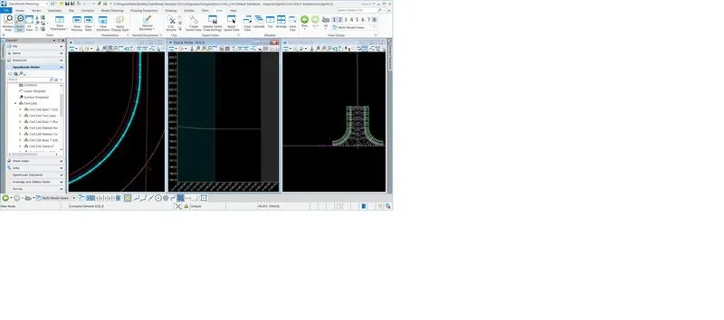
Now hit open , 2 new windows open up with T-intersection default view and T-intersection 3D view. Now go to explorer=>T-intersection dgnlib(default)=>civil cells=>T basic rural=>click on the plan C/l => flyout menu=>open the profile view=> a profile view opens up with a default level.
-
Now do the profile for edge of pavement from the plan => a profile opens up.
-
In order to place the civil cells into a corridor=> Open ORD=>browse corridor basics.dgn ( before that change the file type from dgnlib to cad files)=>open=>new window opens up=>click on the corridor=>flyout menu=>click lock deactivate rule(just to avoid processing all the time).
-
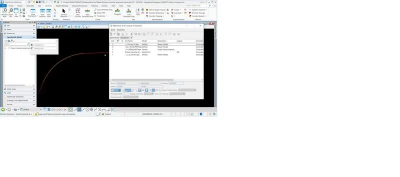
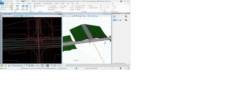
To put the civil cells near the 1st intersection, it is necessary to have the CL and profile for the clipped area. Just hover the cursor on the CL, it can be noted that the Geom temp line has got an active profile. So go to File=>Open project mainline alignment latest.dgn and the file opens up with following attachments as shown below.
-
Now attach corridor basics.dgn to project mainline alignment latest.dgn and turn off the display of project mainline alignment latest, survey topo, eterrain file and corridor basics.dgn. Go ahead and design the CL for the junction .
-
For designing the CL, go to Geometry=>simply select both lines=>hit space key=>copy command=>snap to any nearby points=>keep it back =>come back horizontal=>complex geometry=>define by best fit=>small window opens up=>select complex by edges method and keep everything else default=> Now the CL has been created.
-
Now click on the CL=>flyout menu=>convert to horizontal rules=>now the CL has become a proper horizontal member. Go ahead and turn the display on for ROW existing and the topo and adjust the length of the CL and shorten it with civil rules. Now turn the display off for TOPO and design the profile for this line=>before that assign and FD to this line => go to geometry=>standard=>set FD=>Alignment=>Geom baseline Driveway=>name the element as 'Geom DW'. Now click on the element=>flyout menu=>open profile view.
-
Go to vertical=>draw a profile curve with vertical=>complex by PI=>set the FD active.
Note: Even though the Grade defence is more it can still work for minor intersections.
-
In order to design the intersection, the proposed level of the mainline alignment at the intersection must be known. So, go to vertical=>profile creation =>profile intersection point=> Select the small intersection line 1st and mainline alignment 2nd, reset to complete and magenta line appeared on the profile which is the correct level for the intersection and the profile needs to be redesigned and cross slope to be taken into account while designing
-
For that, go to references, turn display on for corridor basics=>go to geometry=>vertical=>profile creation=>profile intersection point=>select the CL of small intersection=>pick both EOPs of the main line alignment=>finally pick each CLs and reset to complete. Now 2 more magenta points have been appeared on the profile and the intersection must be designed based on the available data and shoulder details to be added later on.
-
Go to vertical and draw simple profile line to match 3 points and observe the slope of it and try to understand the mainline road characteristics of that location. Also, it can be seen that cursor moves equally in plan and profile window and draw simple limit of construction lines based on the location in the plan.
-
Also, it can be noted that length of each line is about 11' and 22 ' required as per the standards. So, extend line each side to make it 22' in each side and draw a smooth profile from the limit of construction to match pavement lane.
-
Now make it smooth by applying curves.
-
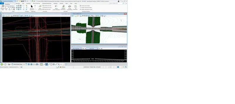
Make the profile active from flyout menu. Now in order to place the civil cell=> go to file =>open corridor basics.dgn=>attach Roadwayplan.dgn=>Open 3 views=>Go to geometry=>Horizontal=>Draw a line at the outer end of the junction section (on both sides). This is done in order to select the Entrance rural civil cell which is having 3 reference lines. Now go model detailing =>place a civil cell=>Entrances=>Entrance rural=>Ok=>Locate 3 reference lines( First active EOP of main corridor, next locate C/L of the junction part and finally locate the outer end line which drawn)=>a cyan colour civil cell appears over the corridor=> click on the brown arrow to arrange the direction and location of the civil cell =>locate the corridor to be clipped message appears but in this context the corridor has already clipped=> so, reset and accept.
-
Note: If the 3D created with errors( for eg: the EOP line which selected might not have a profile in it) or in order to adjust the outer line, then click on that specific line plan (EOP or EOS)view=> flyout menu=>open the profile view=>go to geometry=>vertical=> profile creation=>select=>project profile range to element=>locate the element to project (which is the same line )=>select the plan element to project on to (which is the line just outside of the clipping area and located in line with specific element without profile) , so select it=>project on to ( select the same line without profile)=>select range from start of the clipping area outer line(LHS) to end of the clipping area outer line (RHS). Again, the line created has no profile and the profile must be projected from the nearby inner line towards the outer line. For that click on the outer line (line drawn and projected at outside) => flyout menu=>open profile view. Now go to =>profile creation and project the line of the inner EOP or Eos towards the outer line.
-
Note: if there is EOS or EOP line, go to horizontal=>line=>draw a simple line with the same FD(overlapping or extending beyond the point of contact of existing EOS or EOP on both sides in order to understand the profile of road at end points). Go to vertical and open profile view for the line and do the same procedure described in the above paragraph.
-
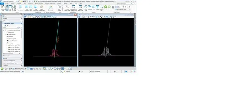
Do the same process for both sides and place the civil cell in the opposite side too. Now the dgn file will look like as shown below.
-
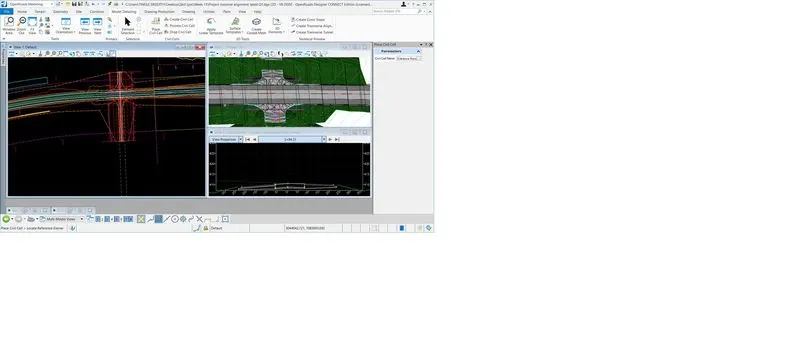
In the above shown image, one lane from EOP to EOS is missing on both sides. In order to model the missing lane, go to corridor = Template=>Create template=>Skill Lync project=>Training 01=> ITL file opens up=> double click on the LHS shoulder=>component properties window=>Display rules=>edit=>delete Not Intersection Left=>Apply=>Ok. Now click on the Buffer component=>display rules=> currently there is no display rules=> so click edit=>select rule=> CL_INT_to left=>later add NOT ( make it NOT CL_INT_to Left)=> come back and check in the next window if it is giving '=true' value which is very important=>apply=> close . Now test the null point for LHS horizontally and make sure that LHS buffer is disappearing when testing. Now repeat the same process for RHS . Once done all the changes, unlock the deactivate rule from the flyout menu. Now select the template flyout menu=>synchronize with library and subsequent 3D model change will be visible as shown below.
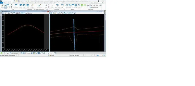
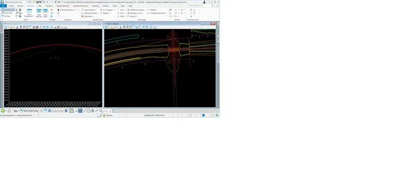
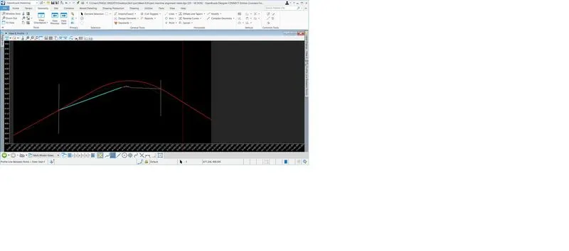
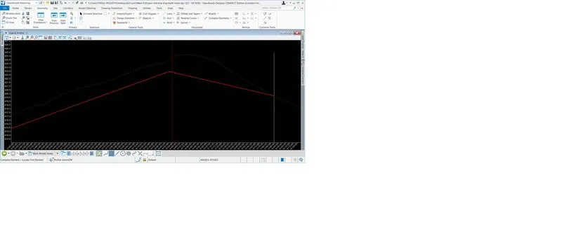
2. Open the DGNLIB file. List out the names of civil cells present in that DGNLIB.
- Open ORD
- Browse 2D seed file, name the file as civil cells, blank page open up
- Now go to model detailing
- Click on civil cells tab
- Click place a civil cells small window open up
- Click on the ... civil cells name, pick place a civil cells/small window open up
- Click on T-intersection dgnlib(default)
- Click on basic T (urban and the template window open up
- Now go to DGN library for this goto file(top left corner)
- Click on settings
- Click on configuration/variable/window opens up/type civil cells/select civil_civil cells dgnliblist/click edit/another window opens up which shows the pathfor the civil cells dgn library (or snapshot the reference for the future)
- Note: Dont edit anything directly in the edit configuration variable
3. List out the References in the civil cell.
- Open the previously created file called civil cells
- Go to the model detailing tab, in civil cells session
- Click on place civil cells
- Click on ... dots
- Small window open ups
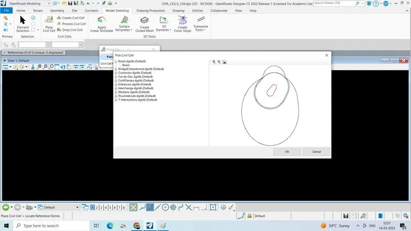
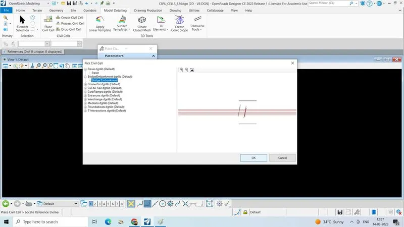
- Open each template listed in the window and the red lines in the window should be designed and placed it in the basic dgn file before placing any civil cells into it.also there should be a terrain file attached to it.
- Thus the civil cells reference can be seen in the file
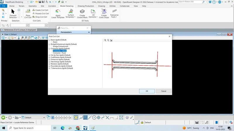
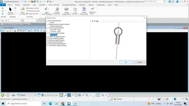
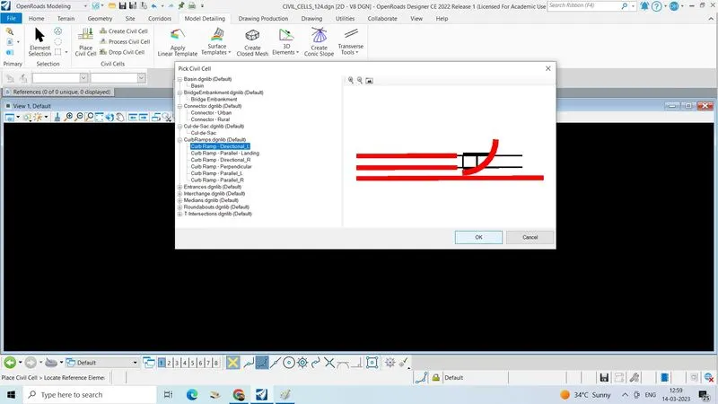
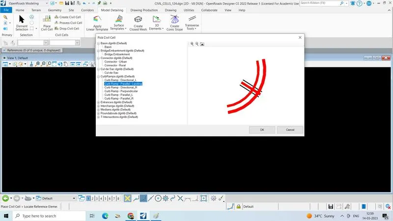
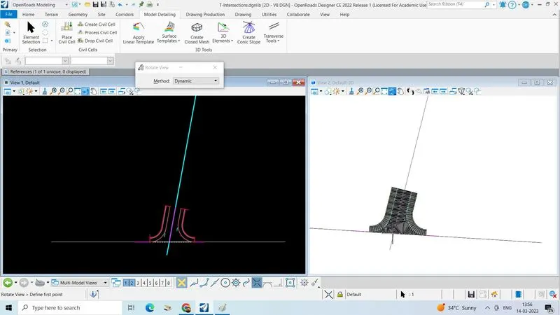
4. On any one civil cell, change the secondary alignment bearing, so that it is skewed by 10ᵒ. Confirm if the civil cell, transitions as per the alignment shift.
- Open ORD,create transitions as per the alignment shift
- In modeling detail tab, click on place civil cells small window open up/click on the (...) click cell name
- Pick civil cells window open up
- Click on basic T(urban) and the template window open up.
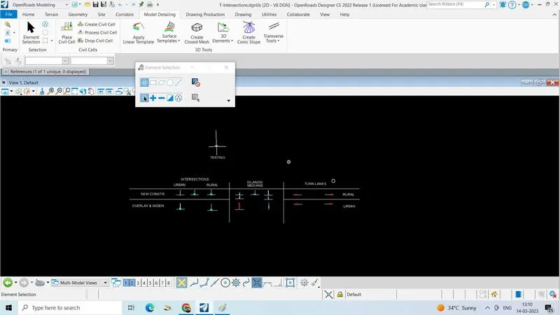
- Now select any template(for example select the rural/new constructions/T-intersection/Zoom in & check the existing angle with the civil rules
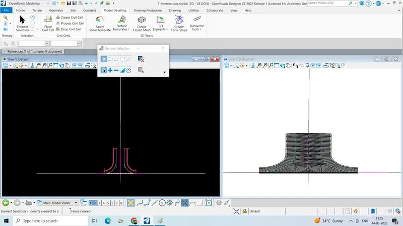
- Now change the angle using the civil rule by 10 degree and subsequent chnages can be visible in the 3D too
- Note: During the design if an intersection drivway needs change in angle the goto geometry file(eg: project mainline alignment file)make change in the angle of the line cells/changes will be applied to the civil cells depends on the feasibility of the available site condition(or solutions determined by the ORD)
- Result: Thus the skew angle can be modified in the civil cells DGNLIB
5. Design 2 driveways alignment and profiles perpendicular to the INT_01 alignment. Refer to the background imagery.
- This has been detailed in Q1.
6. Place appropriate civil cell on one driveway.
- This has been detailed in Q1
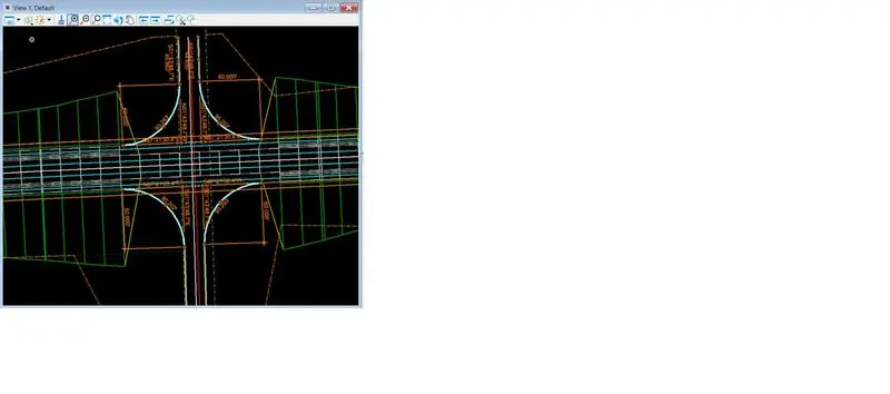
7. Design the second driveway by manual method (using geometry, terrain, modeling tools)
- The detailed procedure for designing the second driveway will be explained below.
- Open ORD=> browse corridor basics.dgn=>file opens up. In this file only the intersecting road C/L has got a profile and EOPs and EOSs doesn't have any profile. As a first step in the manual design, a profile needs to be created for all outer edges.
- Select all the outer lines of the cross junction without the corridor =>hit space bar=>snap it to nearby point and place it back to the exact position.
-
Now go to references=>turn display off for roadwayplan.dgn=>go to geometry =>general tools=>design elements=>create civil rule feature=>FD=>Linear=>Road EOP=>pick all the edge lines=>right click.
-
Now select each element, it can be noted that the elements became civil ruled elements=> Now click on each element=>flyout menu=>open profile view of the first straight element
-
Now go to geometry=>vertical=>element properties=>profile by slope from the element=>No FD=>Locate the element=>locate the reference (which is the CL of the junction road) =>all other properties of the small window remain same=>profile appears on the window=>click on it and make it active by flyout menu. Select the opposite side and do the same.
-
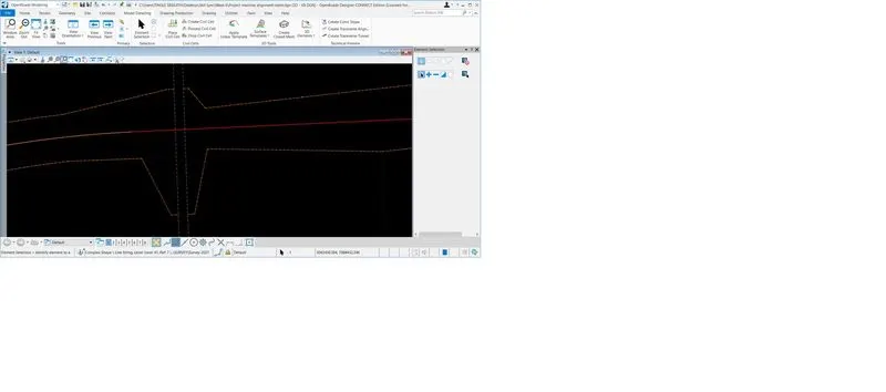
For the below 2 straight line portions, select project profile range to element command to create a profile (use junction CL as projection reference). For the curve sections use profile intersection point command to create profile and make it active.It can be observed that some of the EOP lines are not joined with the mainline EOPs. In order to make it correct, go to same 3D view and with element selection join all the microstation lines and it will be reflected in the plan as shown below.
-
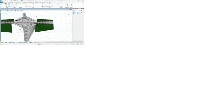
Now go to terrain =>from elements=>pick elements=>pick elements=>pick elements at the edges of the intersection and reset to complete. The 3D triangulated model will be created as shown below.
-
Note: All the edges must have an active profile in order to generate an active surface.
-
Now click on the 3D intersection=> flyout menu=>properties=>turn off the triangles and turn on the contours.
-
Now go to model detailing=>apply surface template=>locate terrain boundary (edges of the newly created intersection) =>select contours=>now the thickness has been assigned to the template.
-
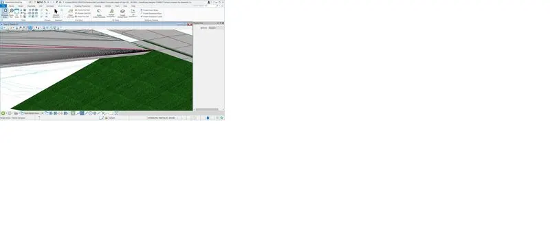
Now in order to fix the end condition errors=> go to linear template=>on the 3d select the element (straight portion edge where the problem) =>click Alt+down arrow key=>pick template window=>select EC combined cut and fill=>now select the curve portion and do the same=> it can be observed that most of the graphics are clear from errors. If there are small patches to be filled further, it can be done by first adding a key station. For that click on apply linear template=>window appears=>try to select the elements (curve junction radius area, it can be noted that selection is not happening ) so come out and right click=>Turn level off by elements=>click on the junction road=>now the thickness layer of the graphics has turned off=> now go to element selection=>expand element selection it can be observed that the element supposed to select is in default mode=>go to reference attachment level display of corridor basics.dgn=> right click =>select any other level=>jump to active (command) and turn off the default=>pick the element=>go to apply linear template =>do the same process as before=>Now the end condition graphics has been created.
-
If further errors exist, it can be resolved by Geometry edit =>edit terrain model=>edit by picking up the additional triangulation=> but it can't be directly selected from 3d because surface applied to it. So, to plan view and select additional triangulation points.
8. Generate component quantities of the Corridor_INT_01.
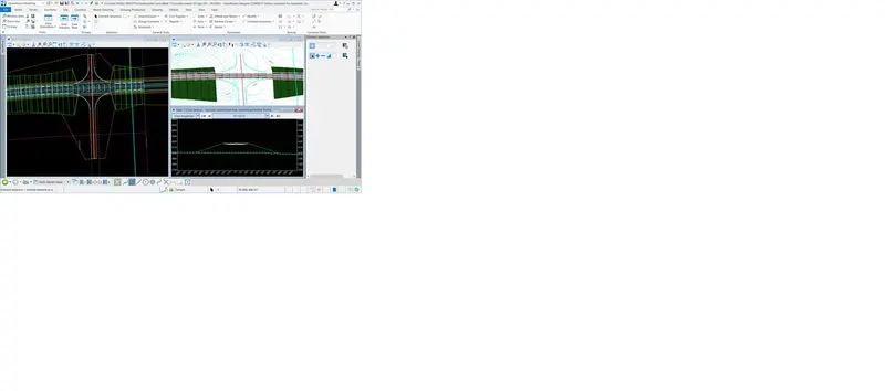
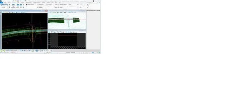
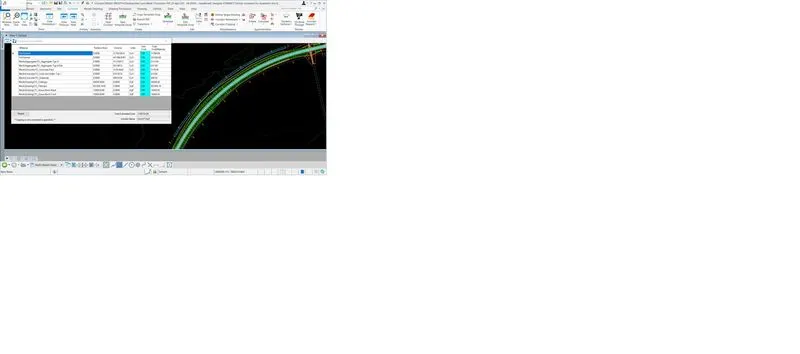
- Open ORD=>browse corridor INT_01.dgn=>go to corridor=>click on corridor reports=>click on component reports=>a table opens up with detailed report of all the components required to construct the road.
-
Note: Unit cost of the items can be changed in order to get the total cost of the work.
-
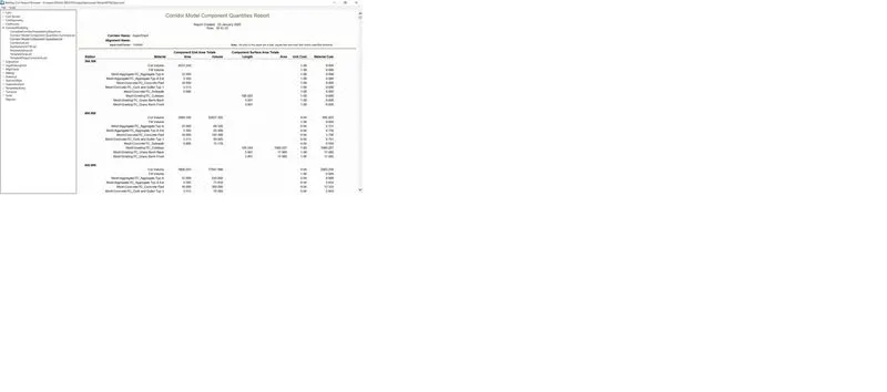
Now click on Reports in component quantities window it will generate a detailed quantity report in the xml format based on stations.
-
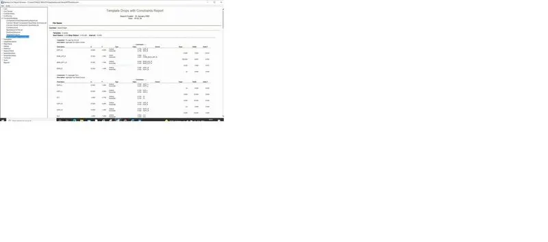
Now go to Review=>Design input reports=>it can be observed that all corridor details, key stations, Template drops, labelled constraints, point controls etc is listed out in the reports.
-
Similarly, Result Reports which is detailed report of the entire corridor, milling report and superelevation report can be generated with ORD.
Note: Element component quantities (under Model analysis and Reports=>Civil analysis) can calculate each component quantities together. For example, this command can add Main corridor +civil cells+ building pad etc and calculate component quantities together.
9. Generate cut-fill volumes and Mass Haul diagram and report for INT_01.
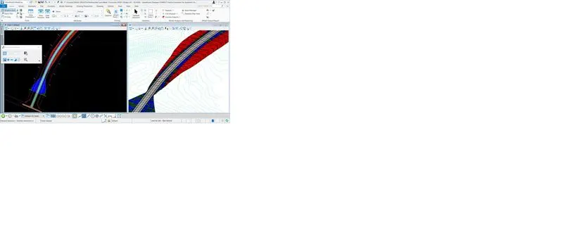
- Open ORD=>Open corridor INT_01.dgn=>Model analysis & reporting. Now in order to create End area volume report, 'cut and fill volume ' must be created. For, that click on the 'cut and fill volume command'=>give everything default=>data point to accept it=>a graphics has been generated with red (fill area), blue (cut area).
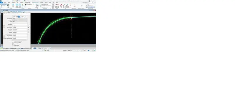
- As the cut and fill volume has been created, now go ahead and click on the Mass haul diagram=>window appears=> give method as Cross section method. But before that the 'Cross section named boundary' has to be created. For that go to 'Drawing Production'=>Named boundaries=>select 'place a named boundary cross section' and give inputs in the window as shown below
- No do a data point and go to plan=>right click view control=>open cross section view=>It can be seen that 'Named cross section boundaries have been created.
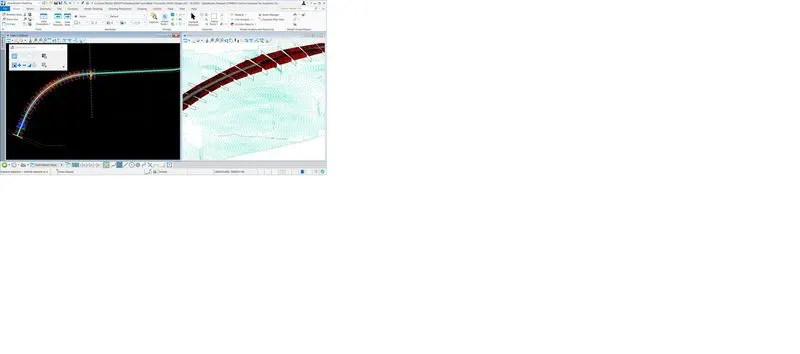
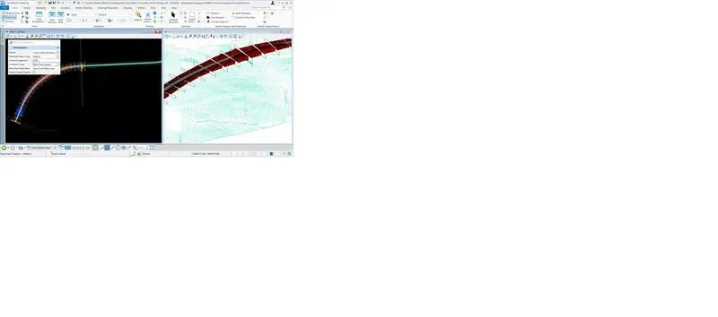
- Now go back to Home=>Model analysis & Reporting=>Civil analysis=>Mass haul diagram=>window appears=>select method as cross section boundary and select the inputs as shown.
10. Generate corridor, legal, input, geometry, earth works XML reports. Save each report in PDF format in the project folder.
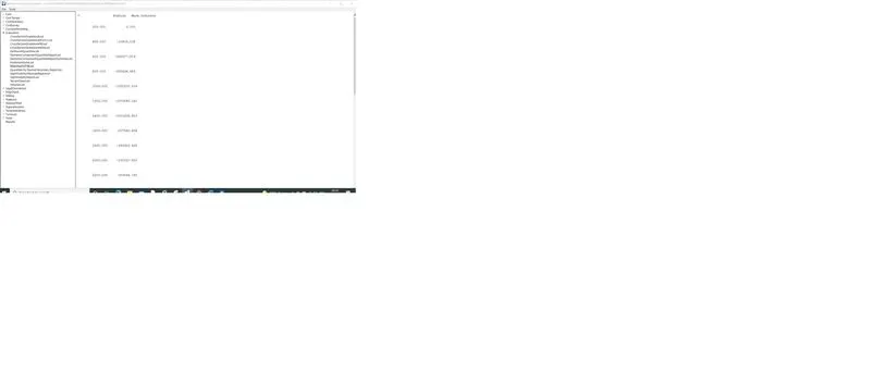
- The procedure for generating the legal, input, geometry and earthworks can be done from either going into
- Home=>Model analysis and reporting or go to Corridor=>Review=>corridor reports which has been explained in Q9.