Week 11 Challenge
Tempreture load
The tempreture difference in bridge level offers restraint for expansion or contraction to bridge. Thus load produced due to restraint is known as tempreture load.
Challange
Here a RC bridge to be constructed in Delhi. As per IRC 6 2017 Maximum tempreture is 47.8 and minimum is - 0.4 degree C in Delhi C.H.O. area. Grade of concrete will be used 40 i.e. fck = 40. The coefficient of thermal expansion of reinforced cement concrete "alpha" is taken as 11.27 X 10⁻⁶ degree per centigrade. Deck of Bridge is 9m span 7m wide and 550mm thick. Pier cap of 6m wide 1.5m high rested on 2.5m circular pier. Box girder dimension is 1500 X 1500 with 300mm web thick ness.
Maximum tempreture in the location as per IRC 6 at the location = 47.8 degree
Minimum tempreture in the location as per IRC 6 at the location = - 0.4 degree
Effective tempreture difference "delta T" = [47.8-(-0.4)]/2 + 10 = 24.10 + 10 = 34.10 degree
Stress due to tempreture= alfa X delta T X E (E from IS 456 = 5000 X squre root 40)
= 11.27 X 10-6 X 34.10 X 5000 * squre root of 40 = 12.15kN/m2
Maximum permissible stress = (2/3) X 0.7 X squre root of fck
= (2/3) X 0.7 X squre root of 40 = 2.95 or 3
Hence the stresses are restricted to 3kNm2"
Maximum tempreture = 47.8 degree
Minimum tempreture = - 0.4 degree
Positive tempreture difference
Tempreture at Top =47.8 degree
Tempreture at Bottom = [ 2.1 / 17.8 ] X 47.8 = 5.64 degree
Temperature difference from top to bottom = 47.8-5.64 = 42.16
Temperature change for Axial Bongation = 30
Modelling bridge structure with given data
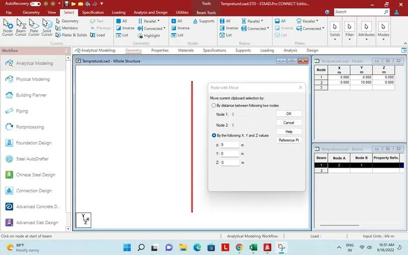
10m beam created for pier.
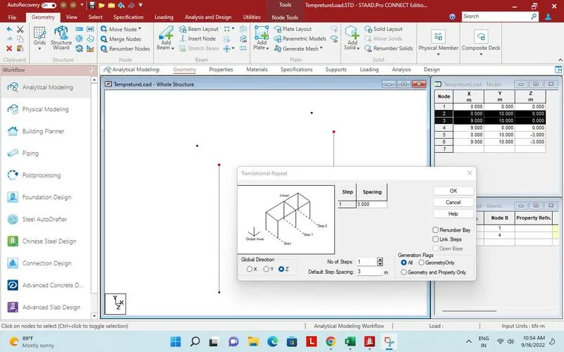
Point created on - Z direction for pier cap.
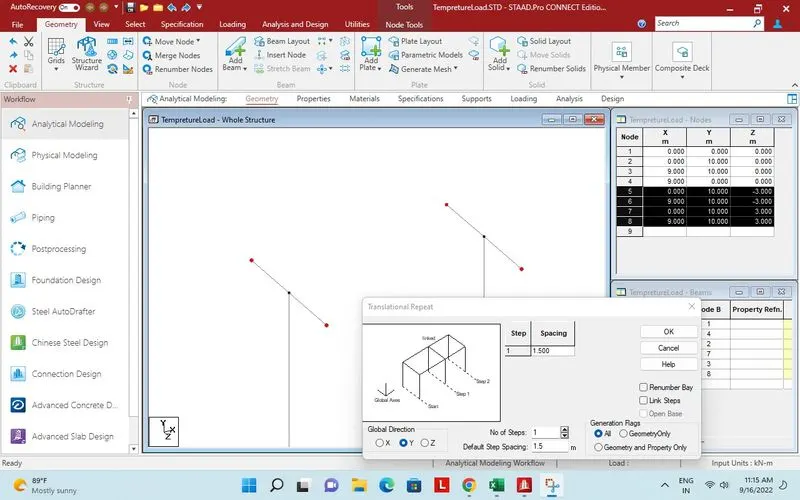
6m pier cap created.
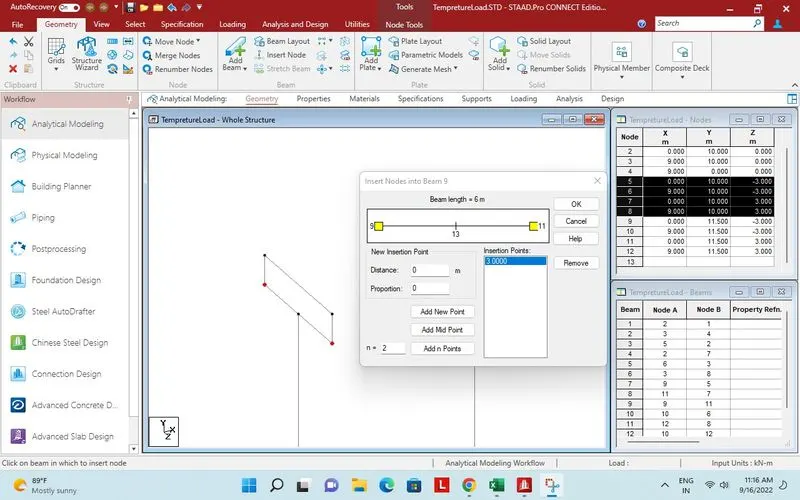
Point inserted in mid for box girder.
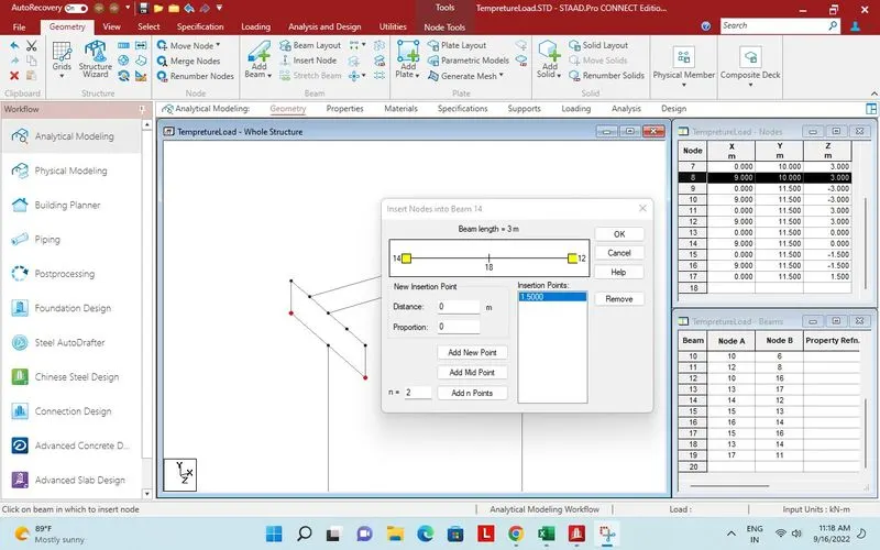
Two long beam placed and point inserted for third.
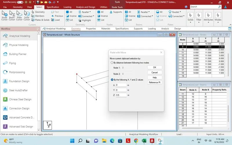
Points created at a distance of 0.5m for plate mesh.
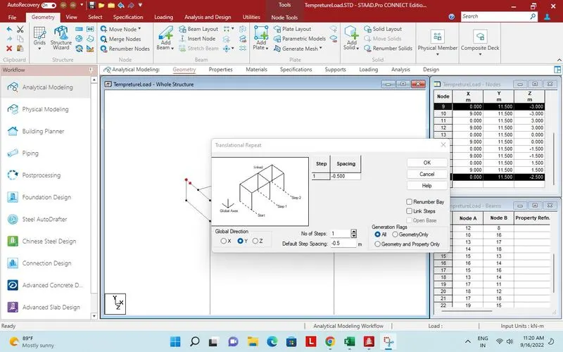
Points translational repeat in - Y direction at a distance of 0.5m.
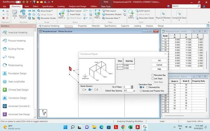
Plate created for Pier cap.
Two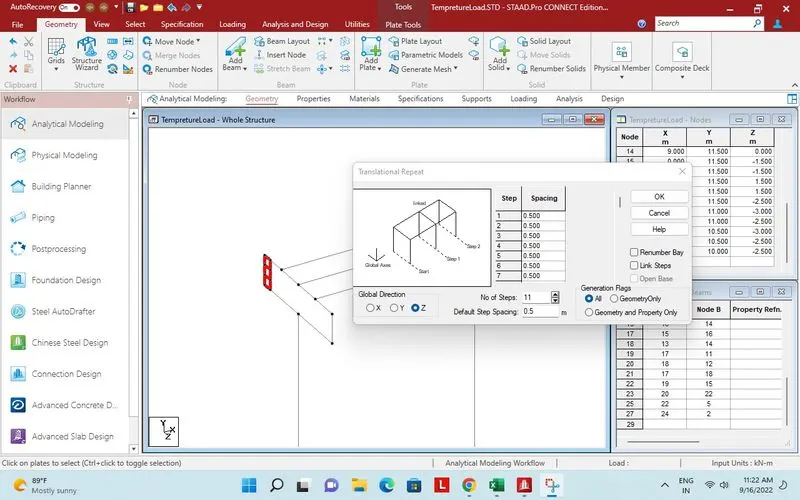
Two more plate added in - Y direction.
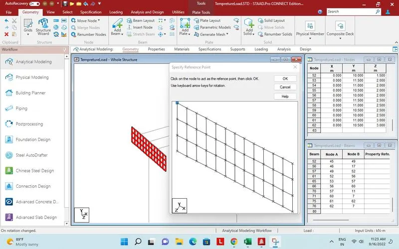
Plates of one pier cap copied with reference point.
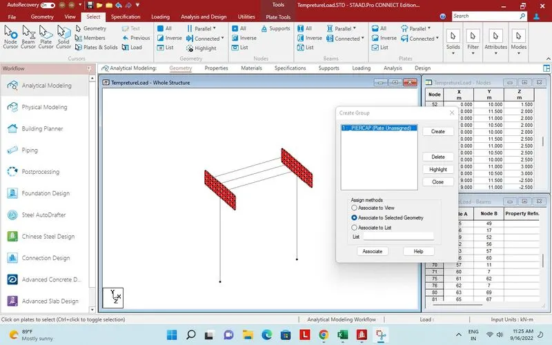
Both pier cap plates are ready.
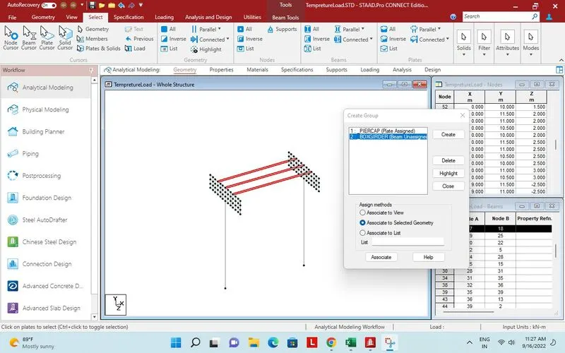
Group created for long beam.
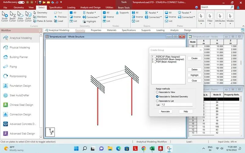
Pier assigned to Group.
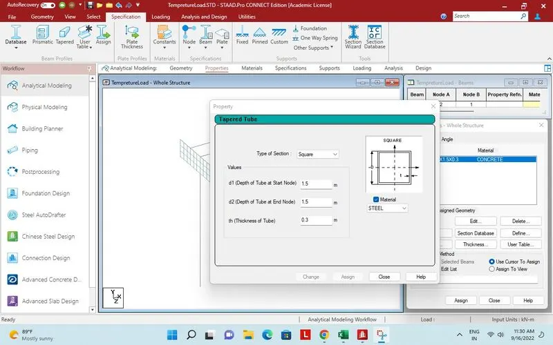
Box girder property.
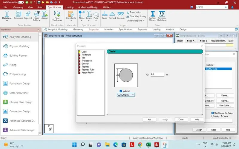
Pier property.
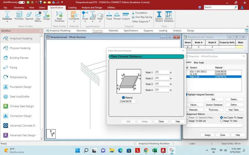
Thickness of Pier cap.
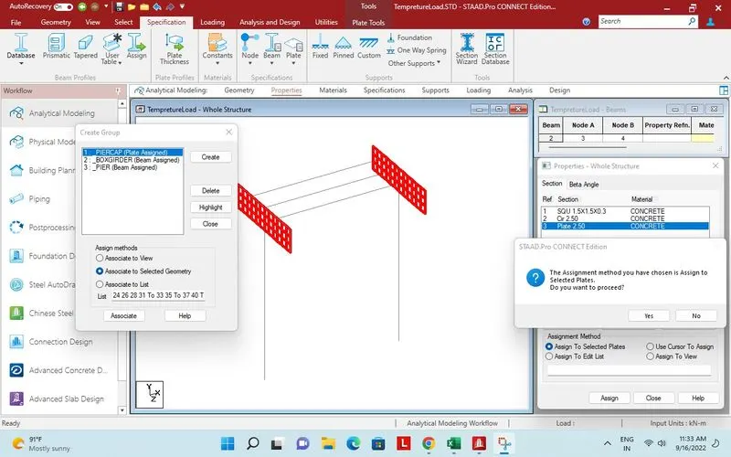
Property assigned to Pier cap.
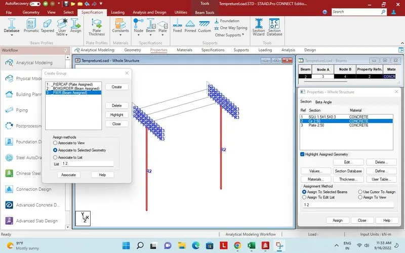
Property to pier assigned.
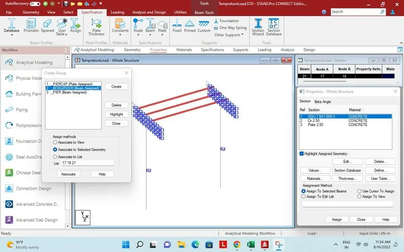
Property assigned to boxgirder.
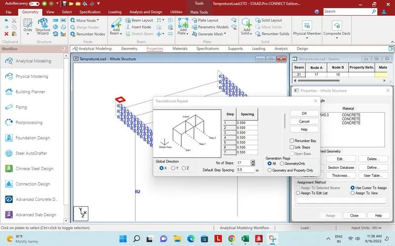
Plate created for deck.
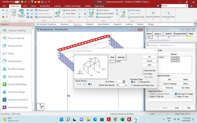
Plates added in X direction by translational repeat.
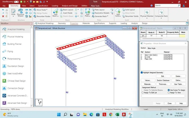
Set of plates created in - Z direction as the deck is 7m wide.
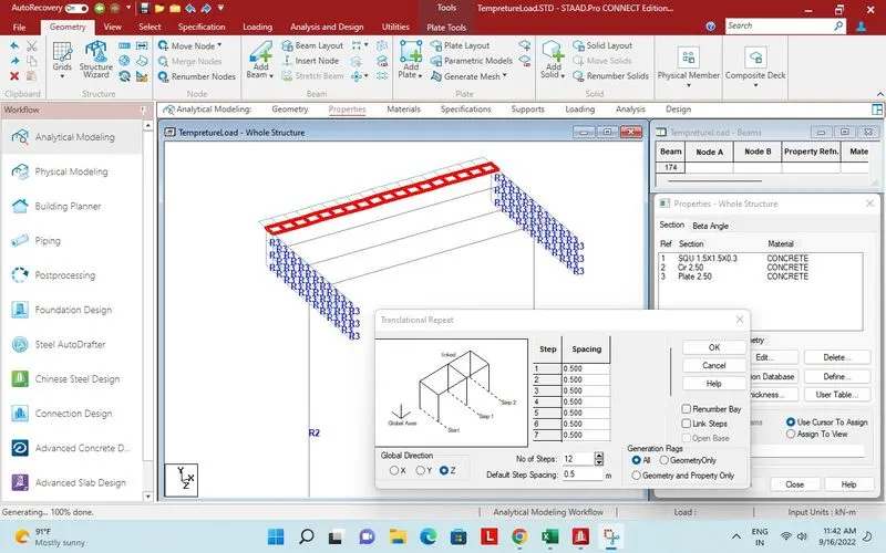
12 set of plates will be added in Z direction
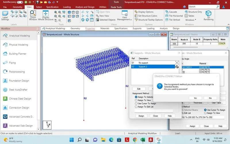
Fix support assigned to pier.
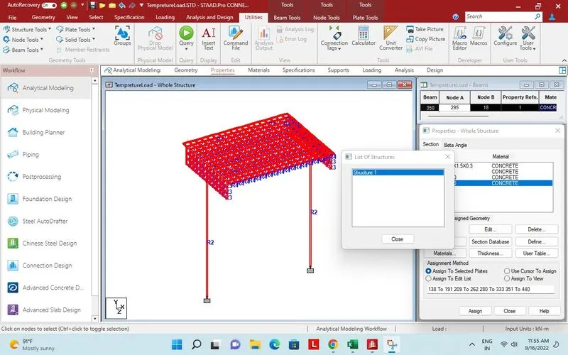
Checked for structure integarity.
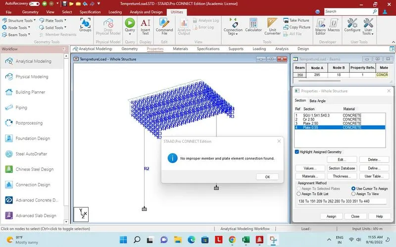
Member and plate connection checked.
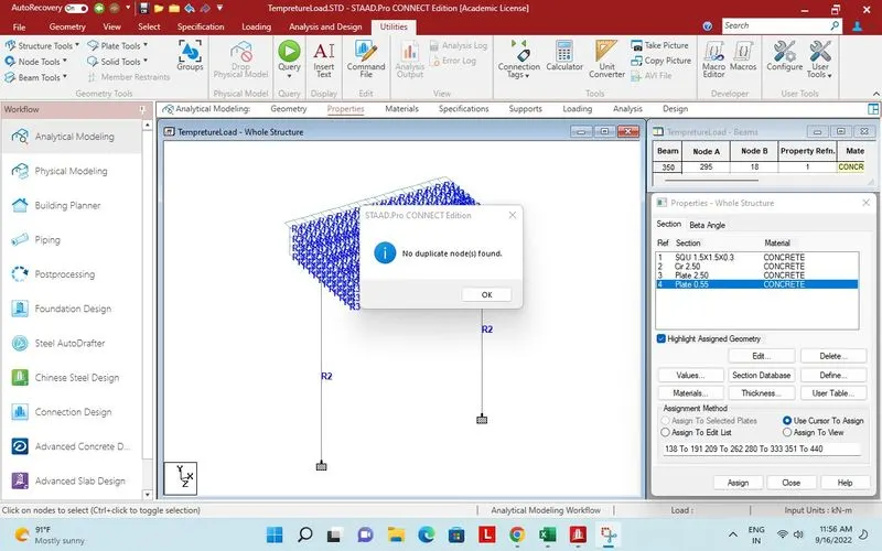
Check for duplicate node.
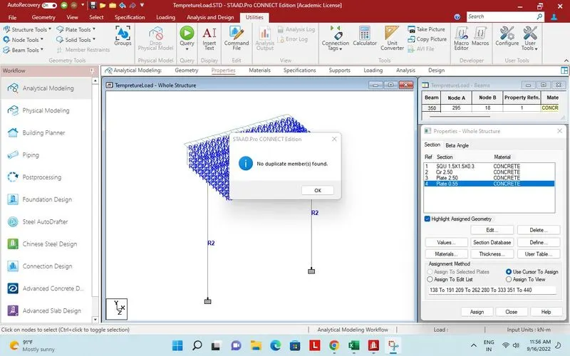
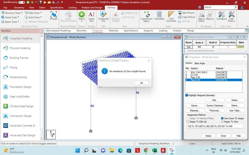
Zero length beam checked.
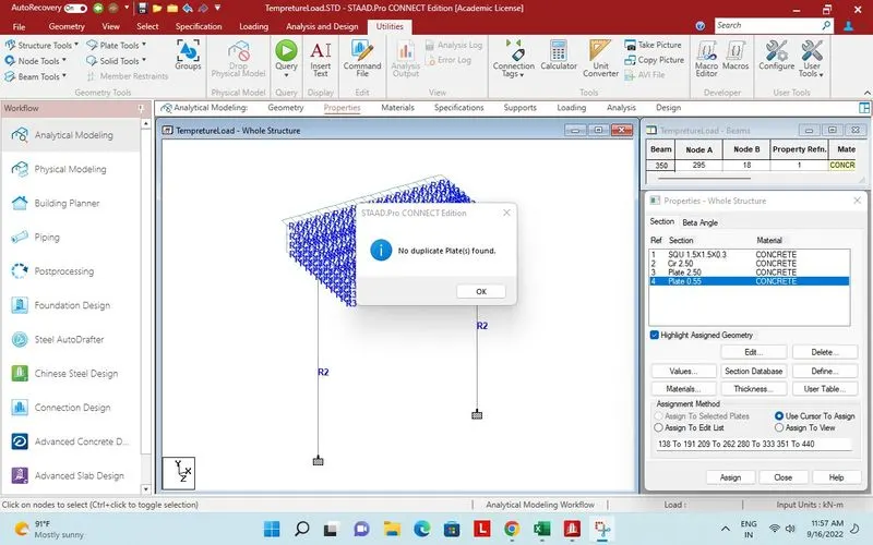
Duplicate plate check.
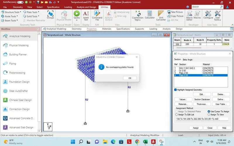
Overlapping plates check.
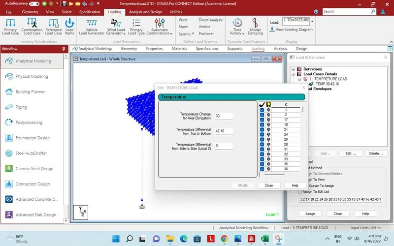
Temperature load input.
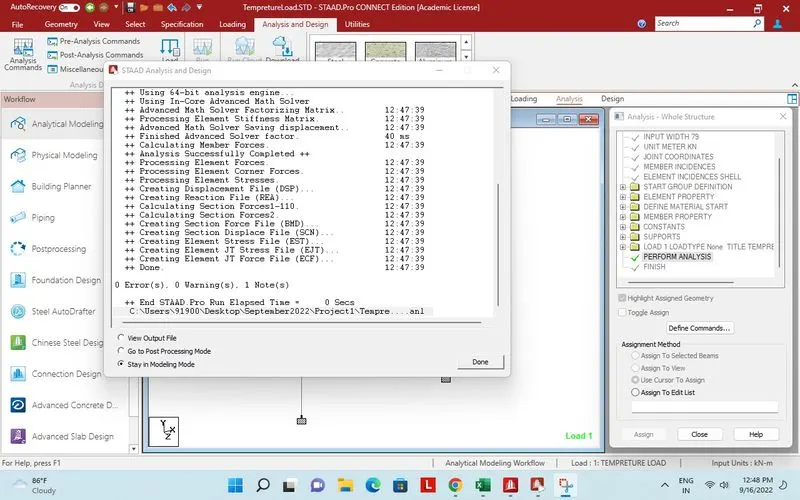
Successfully design and analysis done.
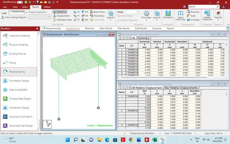
Deflection due to tempreture load on whole structure.
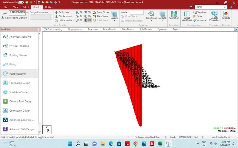
Maximum bending for long box girder.
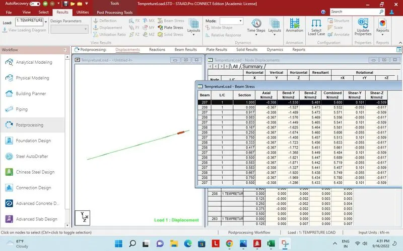
Report bending moment on long beam.
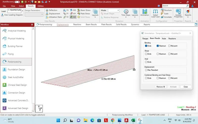
Maximum bending moment for pier.
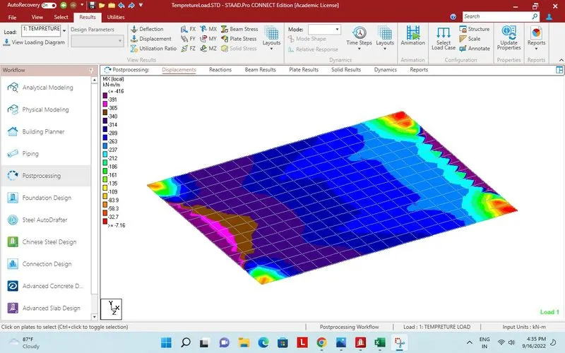
Plate stress in deck slab MX local.
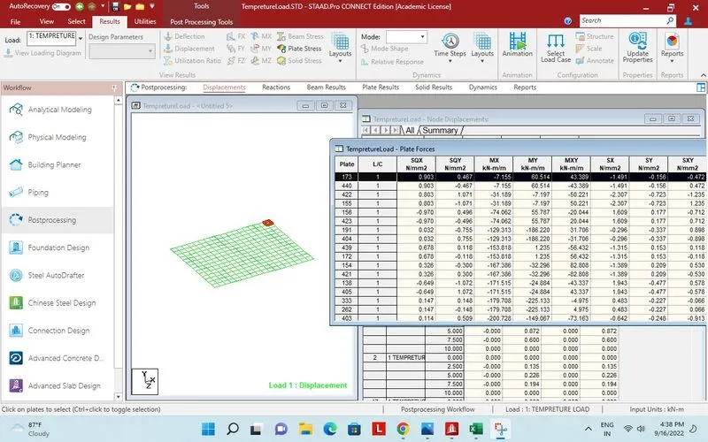
Report for plate stress in deck slab MX local.
Bending moment on one pier.
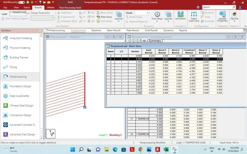
Report of bending moment on Pier.
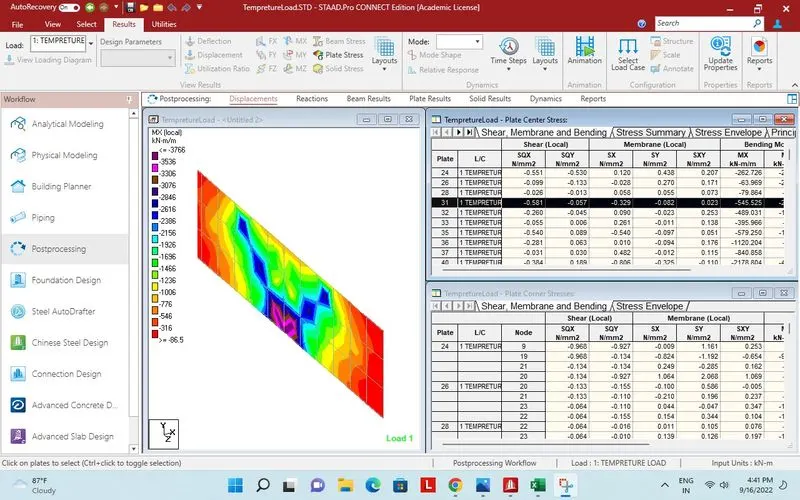
Plate stress MX local on pier cap.
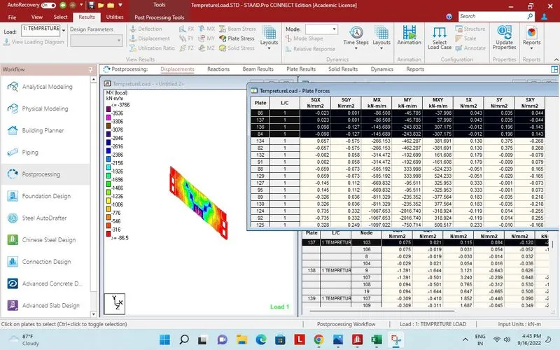
Report plate stress MX local on pier cap.
Bending moment MX local on plates of deck.
Report bending moment MX local on plates of deck.