Week 11 Challenge
Aim and Introduction:-
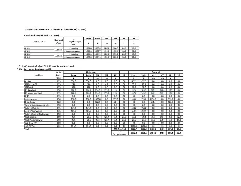
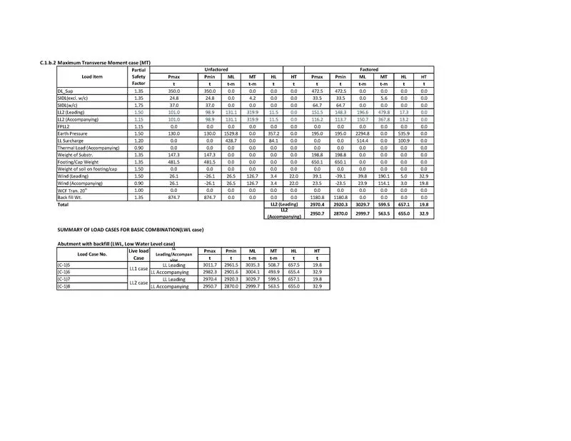
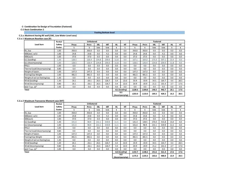
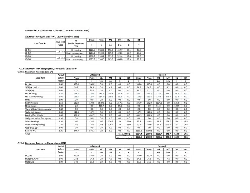
- The aim of this challenge is to determine the types of loads and forces acting on the abutment structure and to design with determining the detail reinforcement drawing for the abutment structure by considering two conditions with various loading criteria. i.e.
- With abutment having backfill
- With abutment having RE wall.
- So first of all the details components, levels with sizes specified from the given GAD has to be taken for the detail designing.
- For designing IRC 6, IRC 78,IS-2911 & IRC 112 has been reffered as follows.
Design Calculation:-
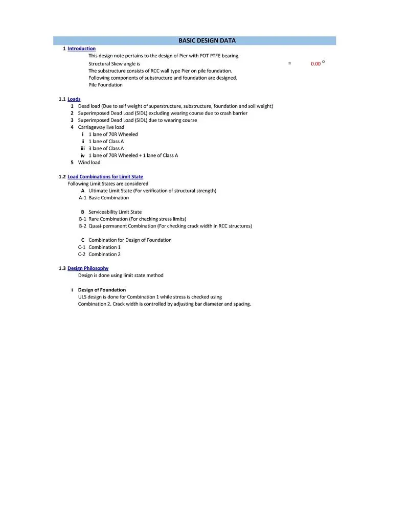
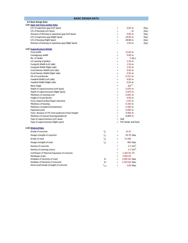
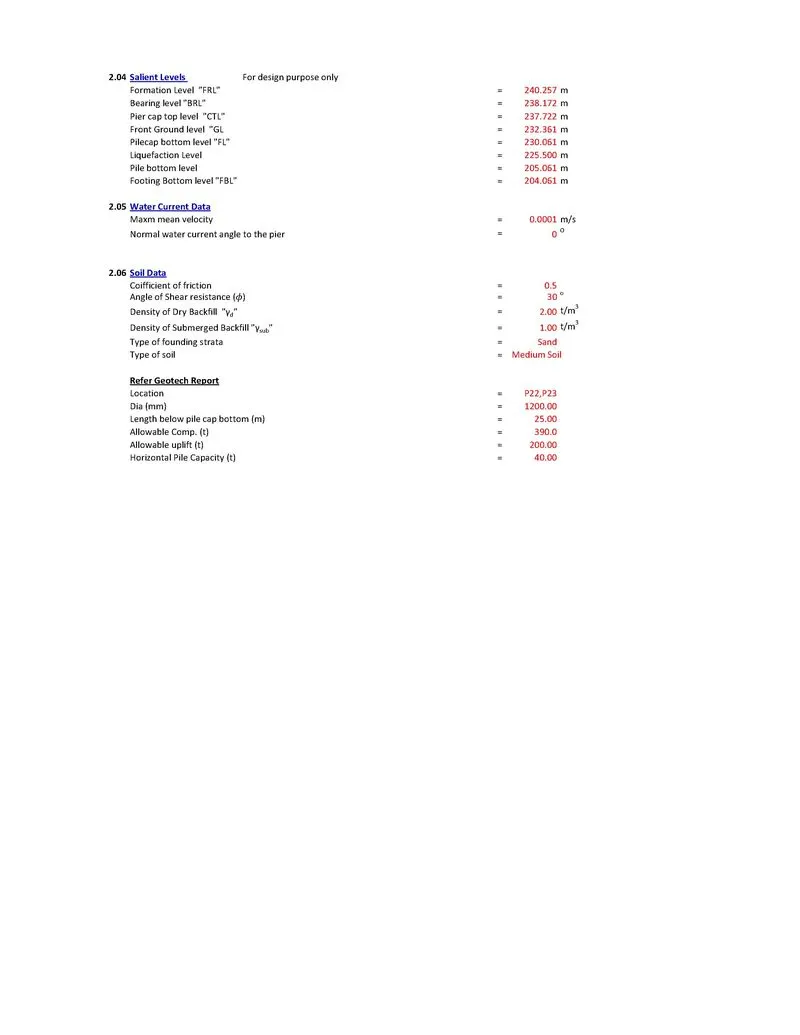
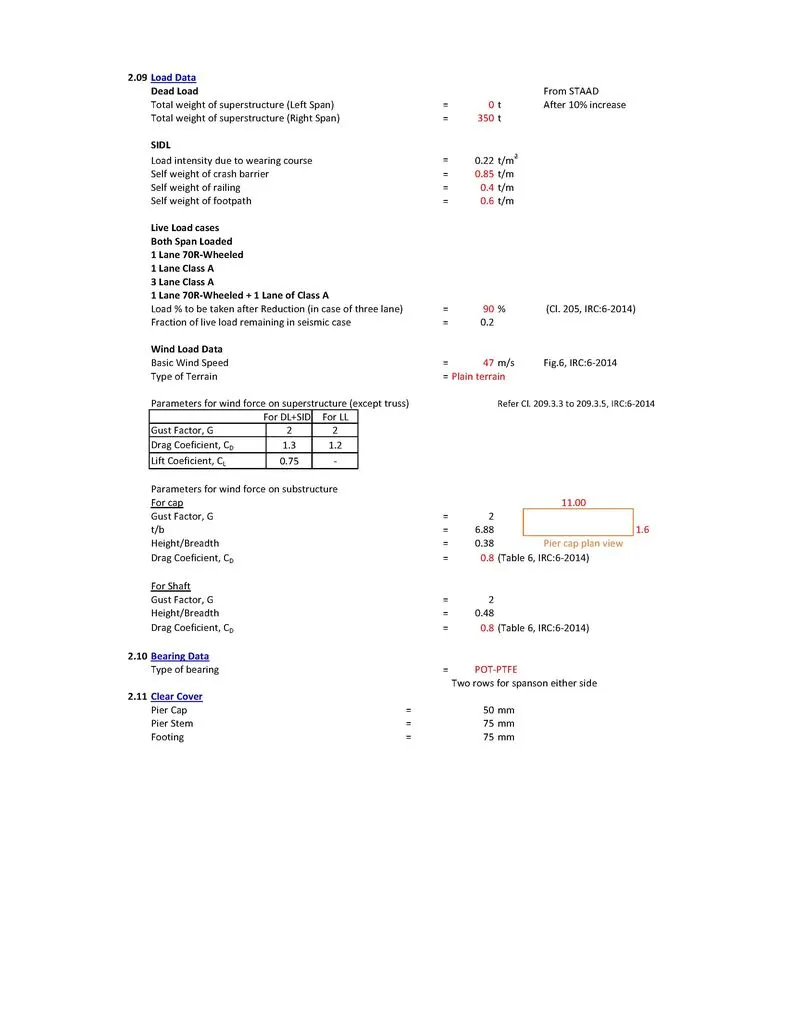
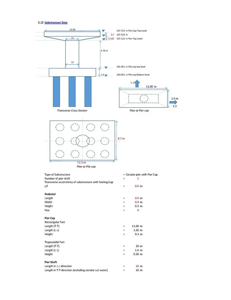
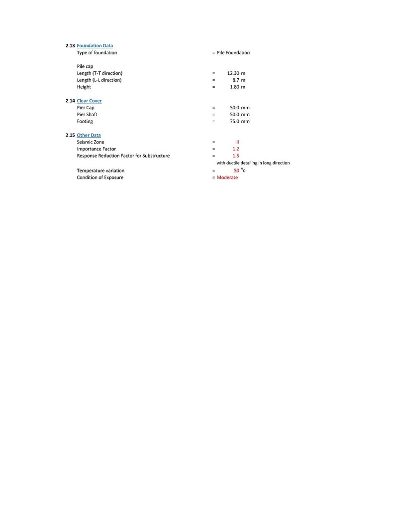
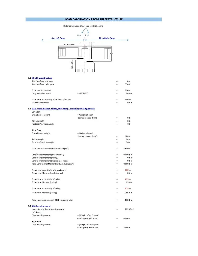
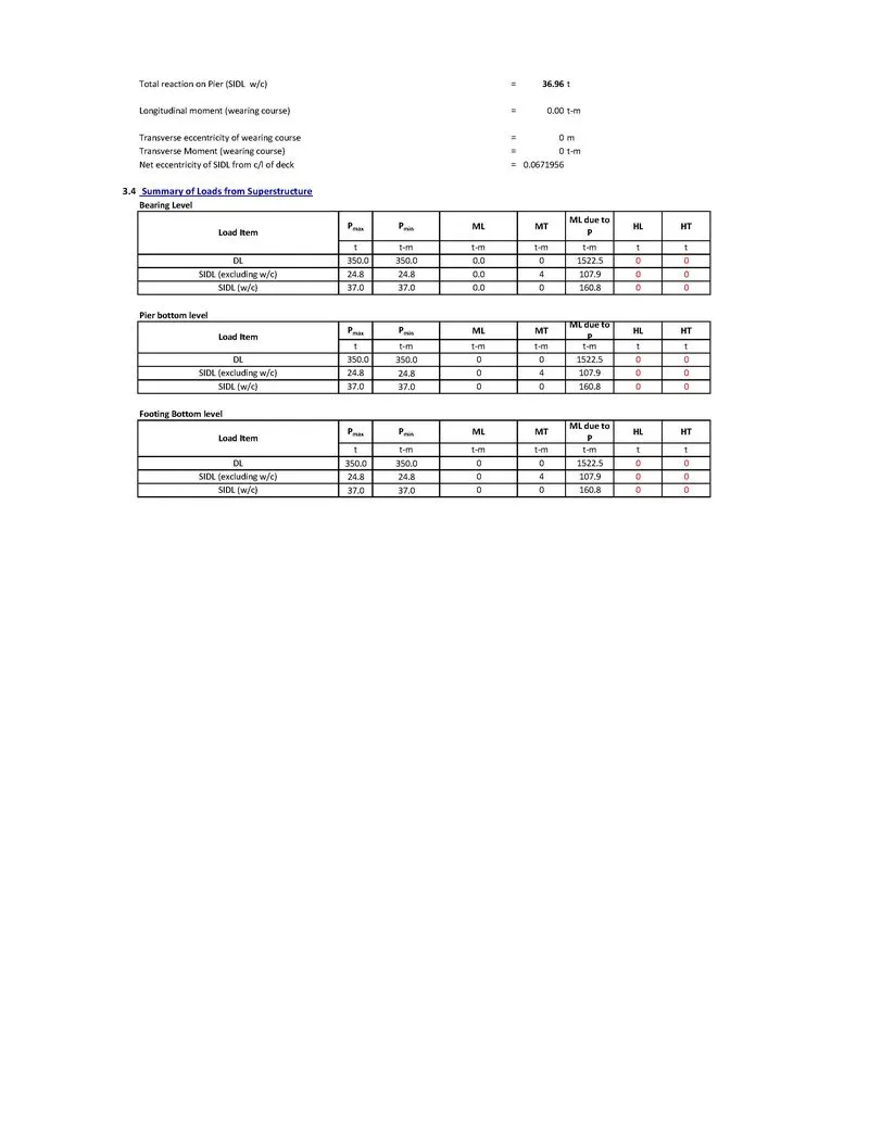

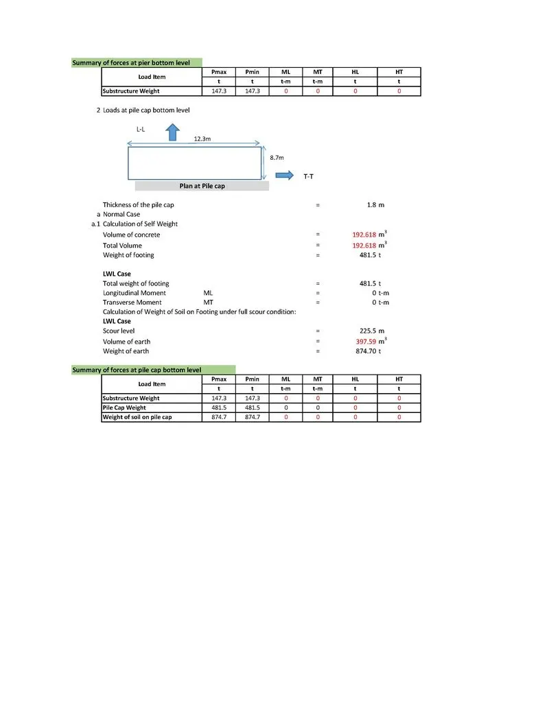
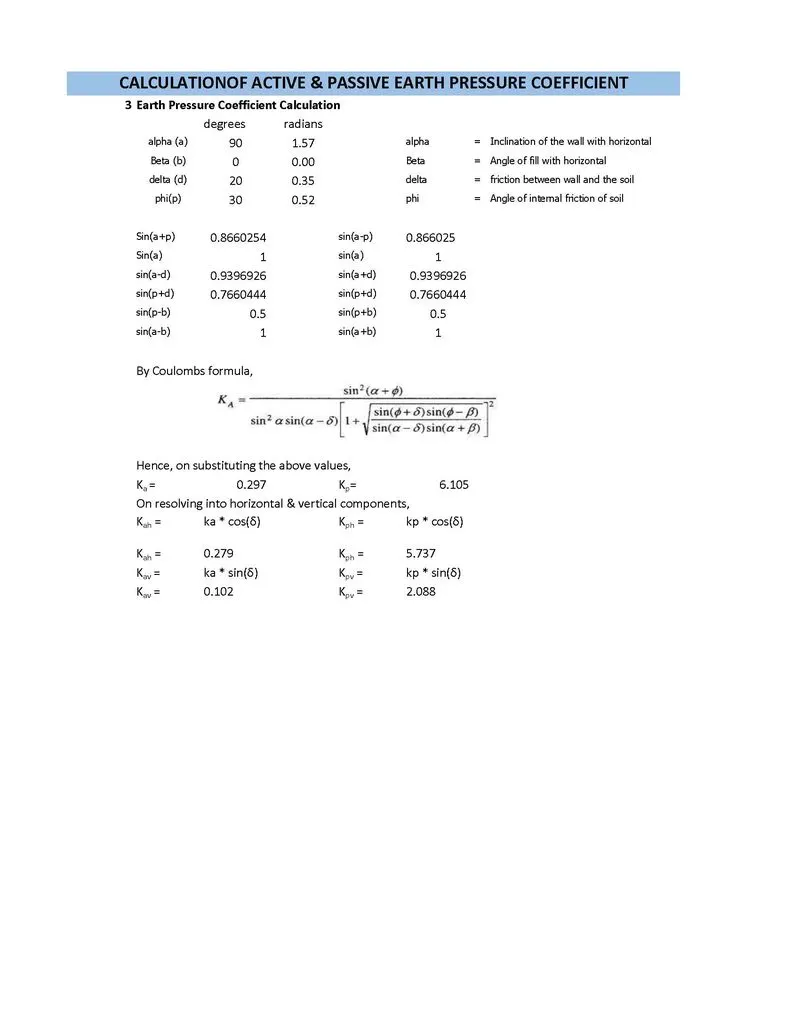
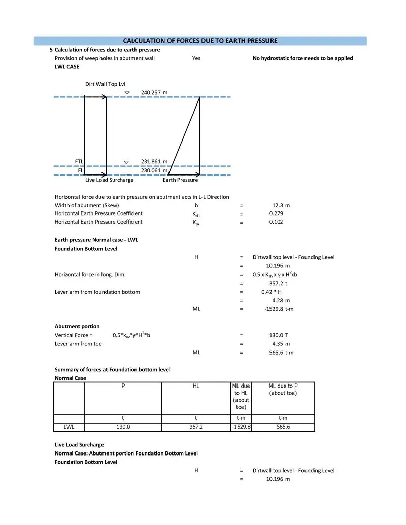
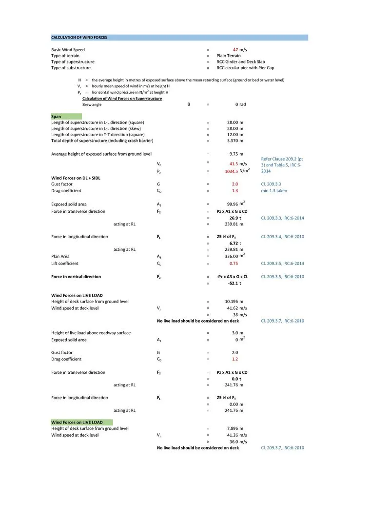
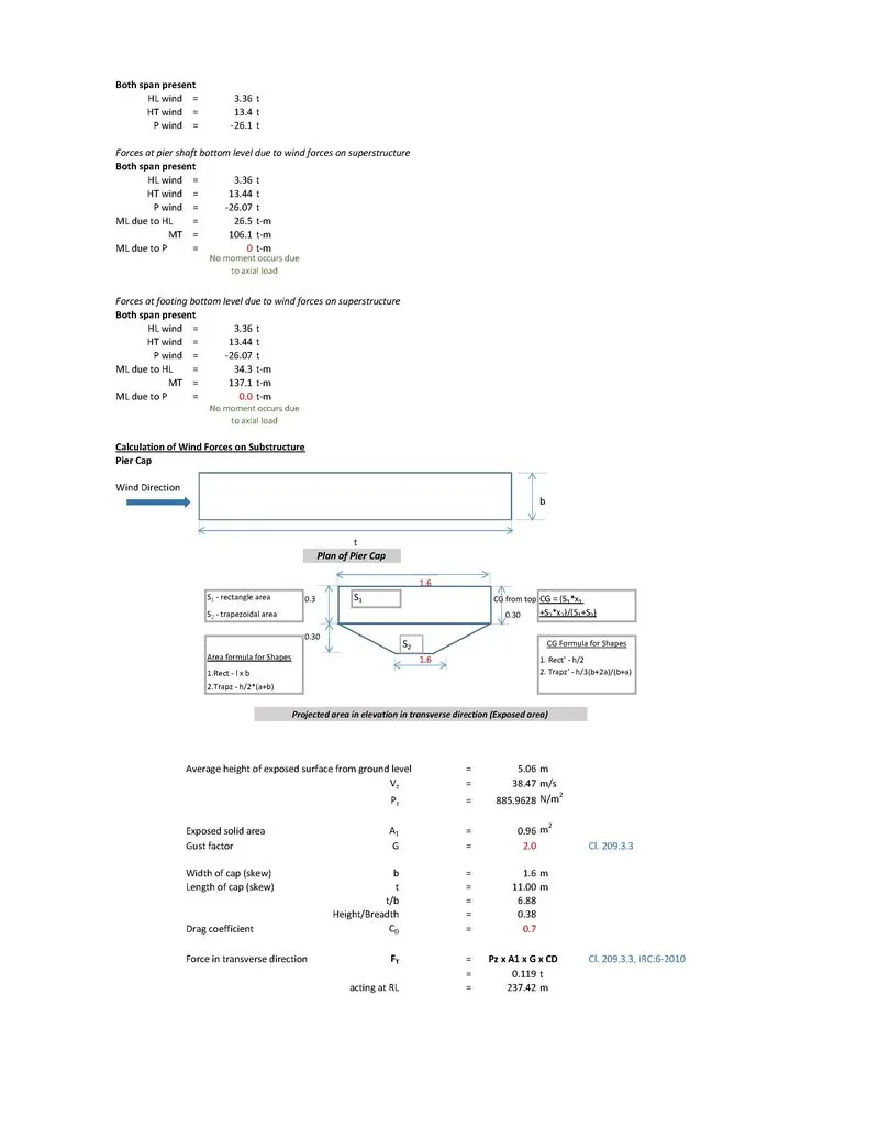
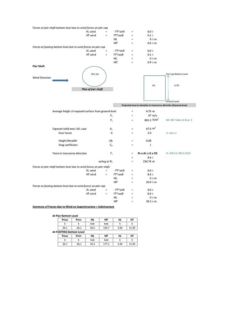

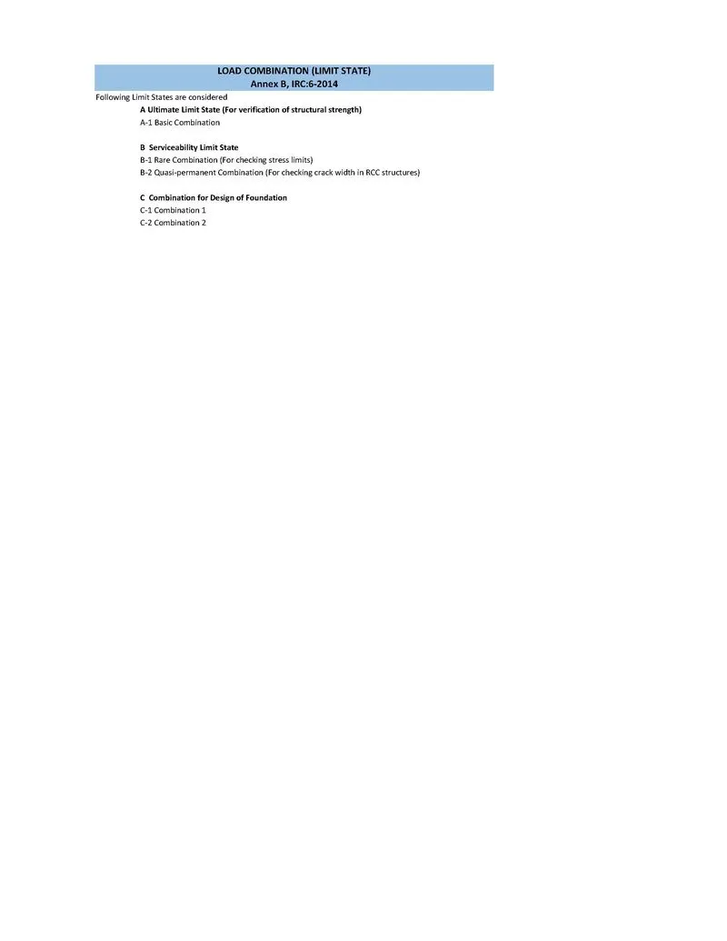
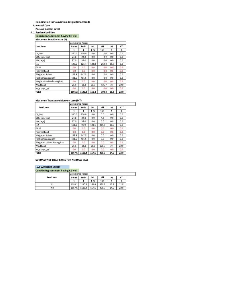
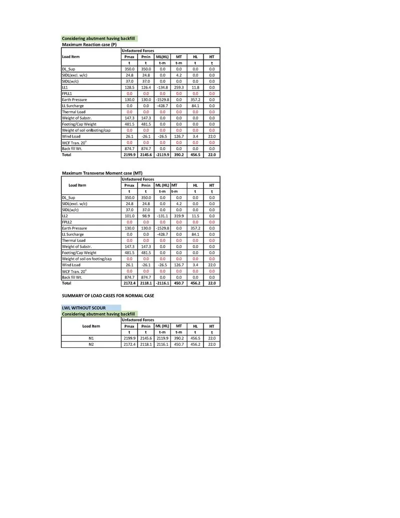
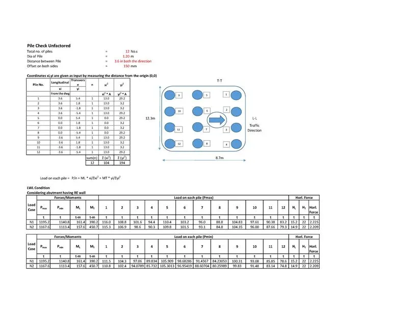
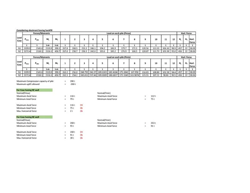
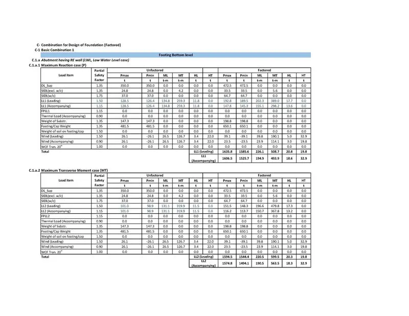
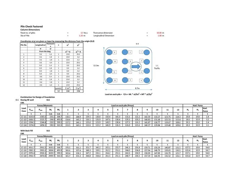
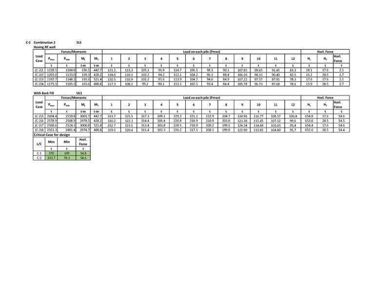
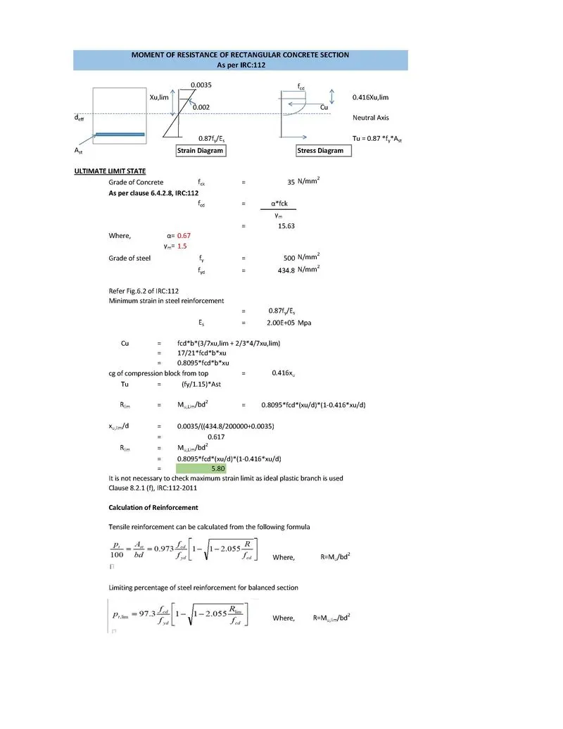
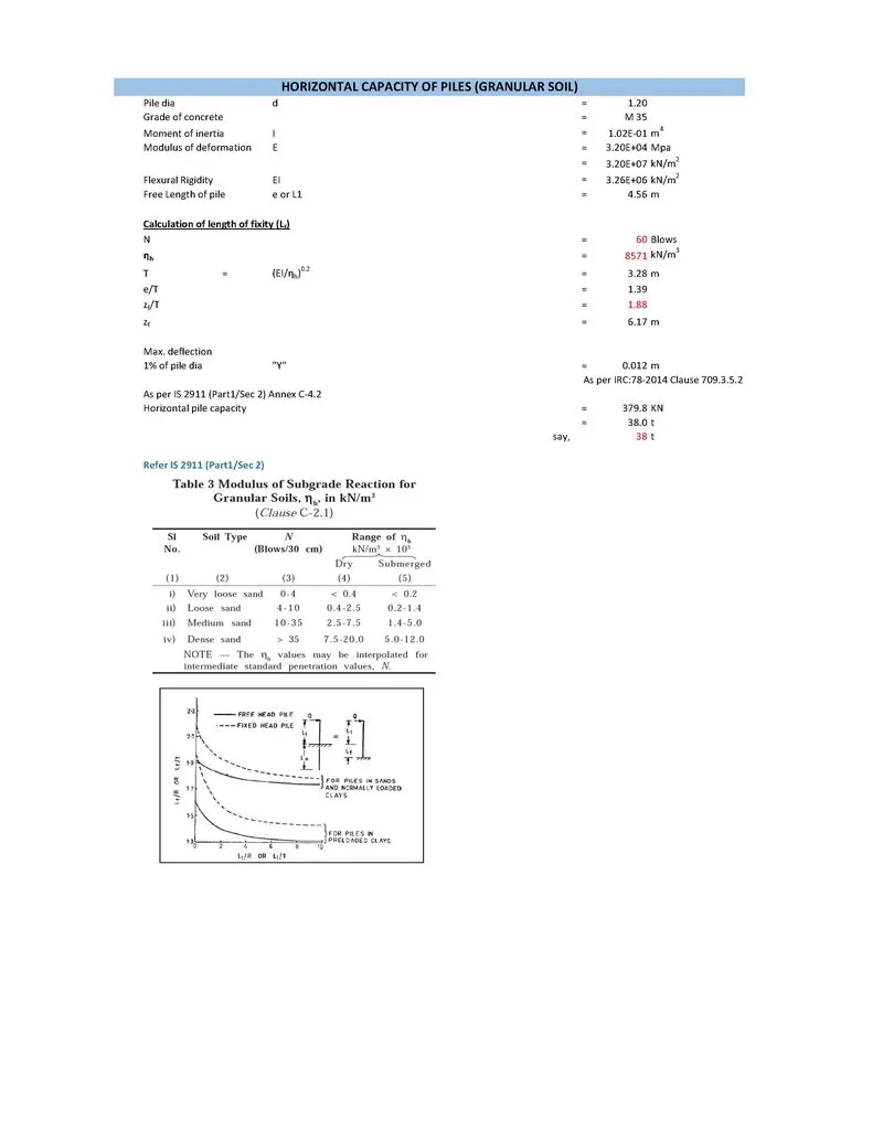
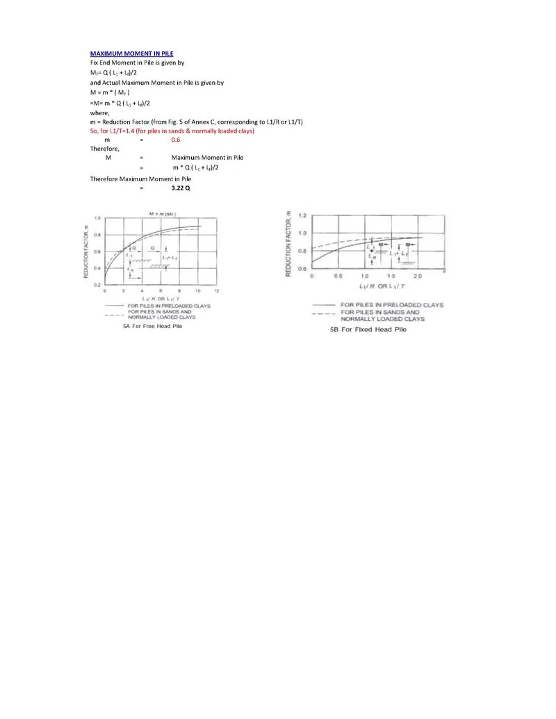
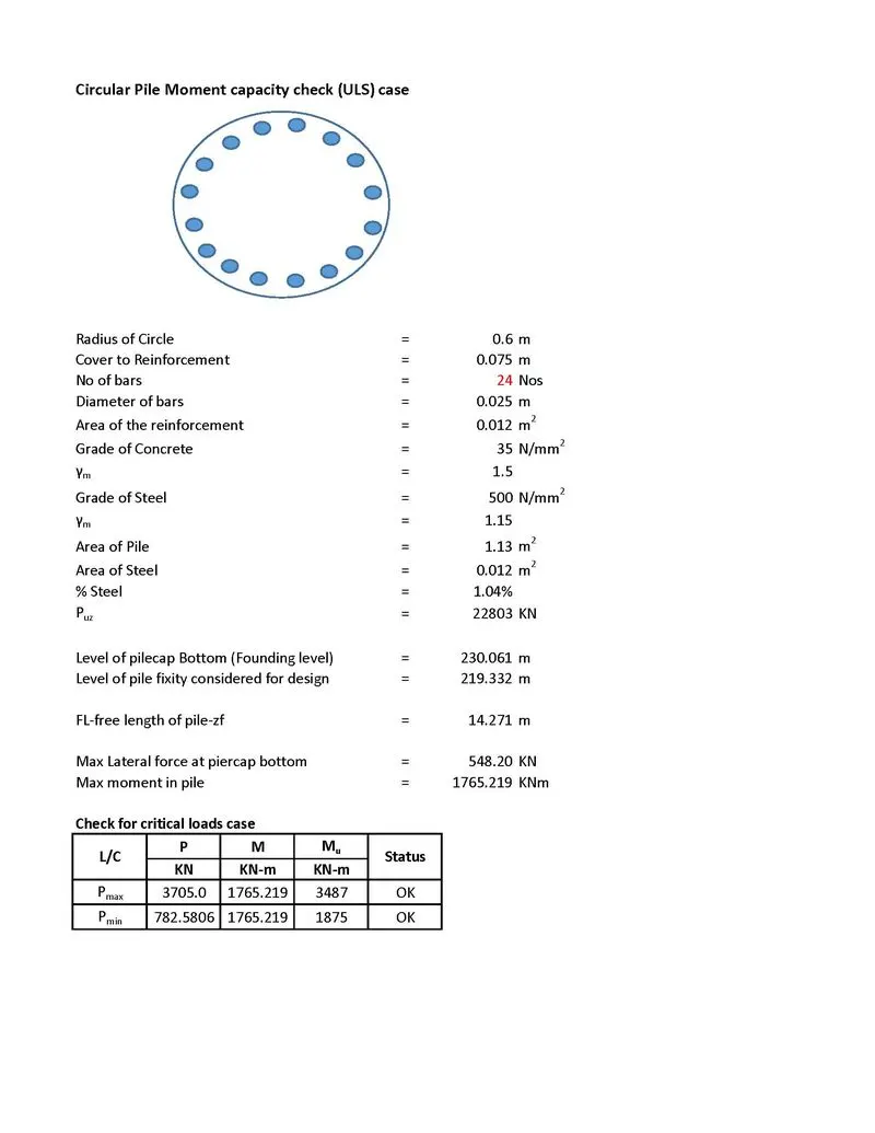
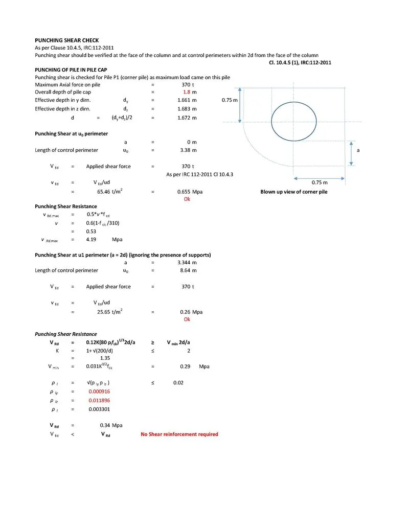
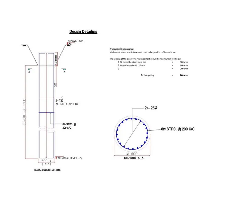
Pile foundations-
- A pile foundation is defined as a series of columns constructed or inserted into the ground to transmit loads to a lower level of subsoil. A pile is a long cylinder made up of a strong material, such as concrete. Piles are pushed into the ground to act as a steady support for structures built on top of them. Piles transfer the loads from structures to hard strata, rocks, or soil with high bearing capacity. The piles support the structure by remaining solidly placed in the soil. As pile foundations are set in the soil, they are more tolerant to erosion and scour.
- When to use Pile Foundation
Following are the situations when using a pile foundation system can be
- When the groundwater table is high.
- Heavy and un-uniform loads from superstructure are imposed.
- Other types of foundations are costlier or not feasible.
- When the soil at shallow depth is compressible.
- When there is the possibility of scouring, due to its location near the river bed or seashore, etc.
- When there is a canal or deep drainage systems near the structure.
- When soil excavation is not possible up to the desired depth due to poor soil condition.
- When it becomes impossible to keep the foundation trenches dry by pumping or by any other measure due to heavy inflow of seepage.
- Types of Pile Foundation
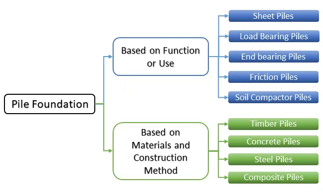
Pile foundations can be classified based on function, materials and installation process, etc. Followings are the types of pile foundation used in construction:
- Based on Function or Use
- Based on Materials and Construction Method
- Timber Piles
- Concrete Piles
- Steel Piles
- Composite Piles
The following diagram is representing pile foundation types discussed above.
-
- Sheet Piles
This type of pile is mostly used to provide lateral support. Usually, they resist lateral pressure from loose soil, the flow of water, etc. They are usually used for cofferdams, trench sheeting, shore protection, etc. They are not used for providing vertical support to the structure. They are usually used to serve the following purpose-
- Construction of retaining walls.
- Protection from river bank erosion.
- Retain the loose soil around foundation trenches.
- For isolation of foundation from adjacent soils.
- For confinement of soil and thus increase the bearing capacity of the soil.
- Load Bearing Piles
This type of pile foundation is mainly used to transfer the vertical loads from the structure to the soil. These foundations transmit loads through the soil with poor supporting property onto a layer which is capable of bearing the load. Depending on the mechanism of load transfer from pile to the soil, load-bearing piles can be further classified as flowed.
- End Bearing Piles
In this type of pile, the loads pass through the lower tip of the pile. The bottom end of the pile rests on a strong layer of soil or rock. Usually, the pile rests at a transition layer of a weak and strong slayer. As a result, the pile acts as a column and safely transfers the load to the strong layer.
The total capacity of end bearing pile can be calculated by multiplying the area of the tip of the pile and the bearing capacity of at that particular depth of soil at which the pile rests. Considering a reasonable factor of safety, the diameter of the pile is calculated.
- Friction Pile
Friction pile transfers the load from the structure to the soil by the frictional force between the surface of the pile and the soil surrounding the pile such as stiff clay, sandy soil, etc. Friction can be developed for the entire length of the pile or a definite length of the pile, depending on the strata of the soil. In friction pile, generally, the entire surface of the pile works to transfer the loads from the structure to the soil.
The surface area of the pile multiplied by the safe friction force developed per unit area determines the capacity of the pile.
While designing skin friction pile, the skin friction to be developed at a pile surface should be sincerely evaluated and a reasonable factor of safety should be considered. Besides this one can increase the pile diameter, depth, number of piles and make pile surface rough to increase the capacity of friction pile.
- Timber Piles
Timber piles are placed under the water level. They last for approximately about 30 years. They can be rectangular or circular in shape. Their diameter or size can vary from 12 to 16 inches. The length of the pile is usually 20 times of the top width. They are usually designed for 15 to 20 tons. Additional strength can be obtained by bolting fish plates to the side of the piles.
- Pre-cast Concrete Pile
The pre-cast concrete pile is cast in pile bed in the horizontal form if they are rectangular in shape. Usually, circular piles are cast in vertical forms. Precast piles are usually reinforced with steel to prevent breakage during its mobilization from casting bed to the location of the foundation. After the piles are cast, curing has to be performed as per specification. Generally curing period for pre-cast piles is 21 to 28 days.
- Cast-in-Palace Concrete Piles
This type of pile is constructed by boring of soil up to the desired depth and then, depositing freshly mixed concrete in that place and letting it cure there. This type of pile is constructed either by driving a metallic shell to the ground and filling it with concrete and leave the shell with the concrete or the shell is pulled out while concrete is poured.
- Steel Piles
Steel piles may be of I-section or hollow pipe. They are filled with concrete. The size may vary from 10 inches to 24 inches in diameter and thickness is usually ¾ inches. Because of the small sectional area, the piles are easy to drive. They are mostly used as end-bearing piles.
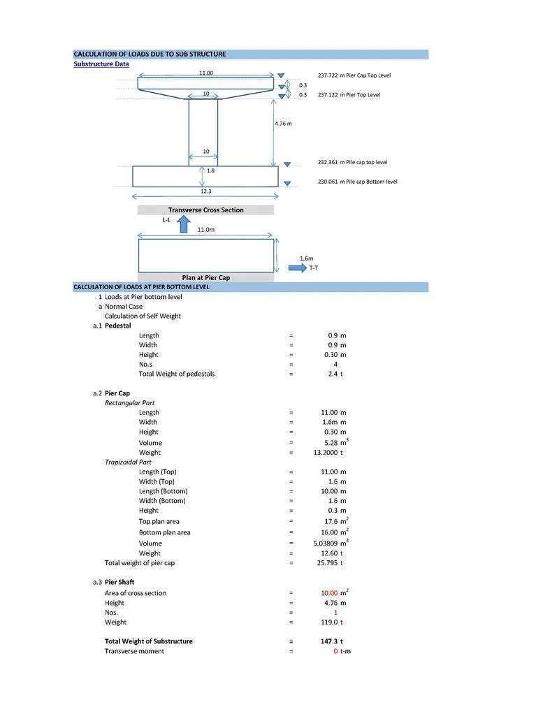
- calculate kg/cumec (poundage) steel quantity in the pile.
Considering 1.2 m dia pile with 20m length
- Calculate the volume of pile.( 3.143 x 1.2 x 1.2 x 20/4 = 22.619 m3)
- Calculate the steel volume at the rate 0.8% of the pile volume.(22.619 x 0.008 = 0.1809 m3)
- Convert the steel volume in weight. Take steel density as 7845 kg/m3 (0.1809 x 7845 = 1419.56 kg, say = 1420 kg)
Design of Pile Cap
Consider the design of a pile cap supporting two pile and a single column on the pile cap.
Data
- Pile Diameter 600mm
- Design Load 3000 kN
- Cover to the reinforcement 50mm
- Grade of concrete 30
- Characteristic strength of steel as 500 N/mm2
- Size of the column on the pile cap 500x500mm
Calculate the dimensions of the pile cap
consider 150mm offset from the pile and space between piles as 2.5 times pile diameter.
Width = 500 + 150 + 150 = 800mm
Length = 2.5 x 600 + 250 + 250+ 150 + 150 = 2150mm
Consider depth of 1000mm and main bar diameter as 20mm
Effective depth, d = 1000-50-20/2 = 940 mm > 750mm; (2.5×600/2) Ok.
Consider truss theory
Tension Force, T = Nl / 2d
T = 3000 x 0.75 / (2 x 0.94 ) = 1197 kN
As = T / 0.87fy
As = 1197 x 1000 / (0.87 x 500 ) = 2752 mm2
Provide 7 T25 (As provided = 3430 mm2 )
Check for Punching Shear
V = 3000 x 103 / ( 4 x 500 x 940) = 1.596 N/mm2
Vall = 0.8 (fcu)0.5 = 0.8 x (25)0.5 = 4 N/mm2 < 5 N/mm2
Hence, punchig shear is Ok
Check for Vertical Line Shear
The critical section of the pile shall be considered as 20% of the diameter of the pile inside of the face of the pile. The following figures extracted from the code (BS 8110) provide a clear location to be considered for shear design.
When this section is considered as a critical section and the spacing between the piles is less than or equals to three times the pile diameter, enhancement (2d/av) for Vc can be considered. Here, av is the distance from the face of the column to the critical section.
In this example, we considered only two piles as shown in the following image.
Vc and be calculated from Table 3.8 of BS 8110 based on the 100As/bd value.
100As / bd = 100 x 3430 / ( 1000 x 940 ) = 0.365
Vc = 0.446 N/mm2
Enhanced shear capacity ; (2d/av)Vc
(2d/av)Vc = ( 2 x 940 / 320 ) x 0.446 = 2.62 N/mm2
Desing shear stress = 1500 x 103 / (1000 x 940) = 1.596 N/mm2
Hence Ok.
Calculate Area of Distribution Steel
Consider the minimum reinforcement requirement.
100As / Ac = 0.13
As = 0.13 x 1000 x 1000 / 100 = 1300 mm2 / m
Provide T16@150 mm c/c (As Provided = 1340 mm2
Area of Horizontal Binders
Provide 25% of the design reinforcements
As binder = 0.25 x 2752 = 688 mm2
Provide T12@150 (As provided = 754 mm2 )
Similarly, other types of pile caps can also be designed following the same procedure. However, when the number of piles is increasing in a pile cap, the manual calculation becomes more complicated. Computer packages could be used for ease of design while verifying the design outcome with simple calculations.