Week 11 Challenge
AIM :- To calculate the temperature load on the RC bridge and then after that apply that load in stadd pro to analyse and results.
LIVE LOAD CALCULATION:-
Given:
Span of the bridge = 9 m
Width of deck slab = 7 m
Thickness of deck slab = 0.55 m
- Maximum temperature in the location as per IRC 6 Isotherm at the location = 47.5 degrees
- Minimumm temperature in the location as per IRC 6 Isotherm at the location = -2.5 degrees
- Effective temperature difference = [(45 - (-2.5)] / 2 + 10
= 33.75 degrees
Stress due to temperature = alpha x delta T X E
= 11.27 X 33.75 X 5000`ROOT`40
= 12.02 KN/m2
Maximum permissible stress = (2/3) * 0.7 `ROOT`fck
= 2.95 kn/m2
Hence the stresses are restricted to 3 kn/m2
- Maximum temperature = 47.5 degree
- Minimum temperature = -2.5 degree
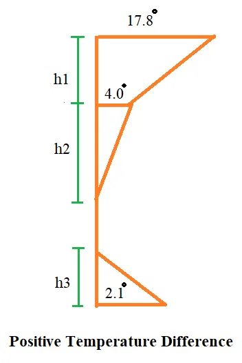
- Positive temperature difference
- Temperature at top = 47.5 degree
- Temperature at bottom = (2.1 / 17.8) x 47.5
= 5.60 degrees
- PROCEDURE:-
1. Firstly a node is created.
2. After that with the help of translational repeat the frame of bridge is created.
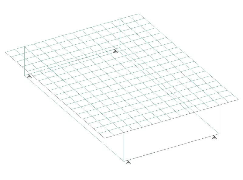
Figure Bridge frame is created with the help of node using translational repeat option
3. The bridge deck is created by using the mesh size of 0.5*0.5 m. The thickness of deck slab is 0.55 m
4. A roller support is created at the base of the box girder at a distance of 0.25 m.
5. Cross beam of size 0.6 m * 1.2 m is created.
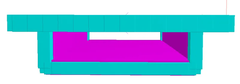
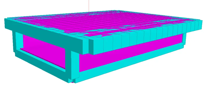
Figure 3D view of box girder bridge
- LOADING
Firstly self weight i.e gravity load of -1 is applied on the whole structure
Loading-----load case details-----ADD-----TEMPERATURE LOAD ------
Then load combination is defined by taking FOS of 1.35 for dead load and 1.5 for temperature load.
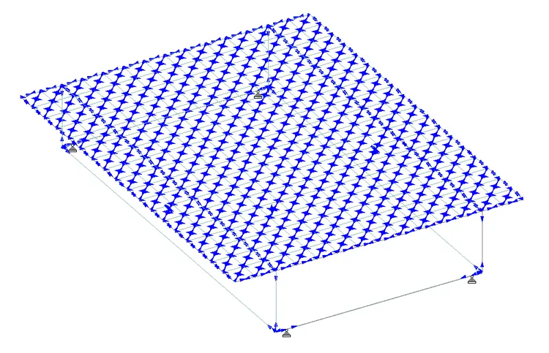
Figure Defined loading condition
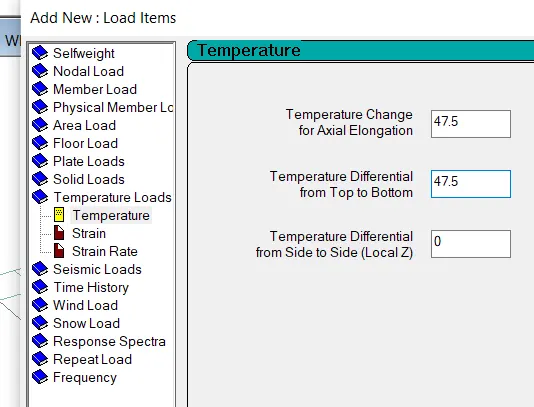
Figure Loading diagram of Temperature Load
- RESULT ANALYSIS:-
1. STATIC CHECK:- Static check is ok as the difference between load and reaction is zero.
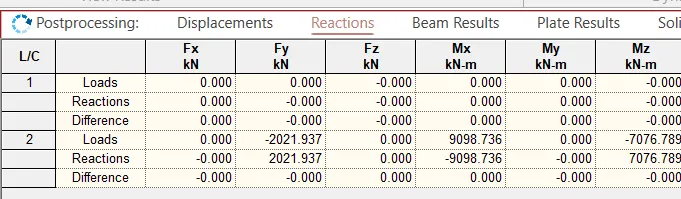
Figure Static check
2. DEFLECTION:- Maximum deflection of the structure is 4.6 mm in Z direction at node 157.
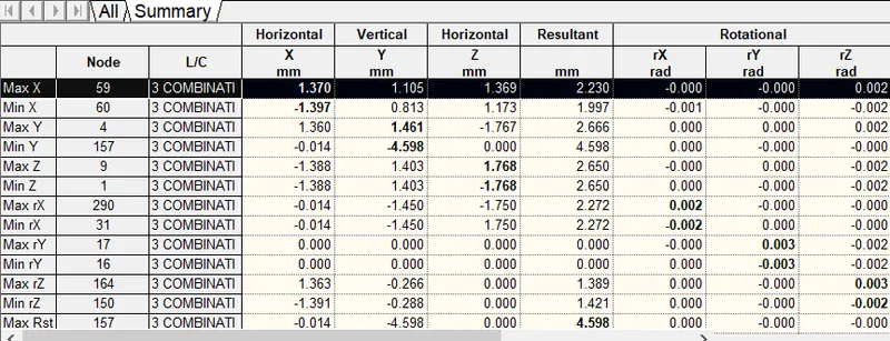
3. REACTION:-
| Horizontal | Vertical | Horizontal |
| Fx (KN) | Fy (KN) | Fz (KN) |
| 2894 | 682.50 | 4692.09 |
| Moment | Moment | Moment |
| Mx (KN-m) | My (KN-m) | Mz (KN-m) |
| 0 | 0 | 0 |
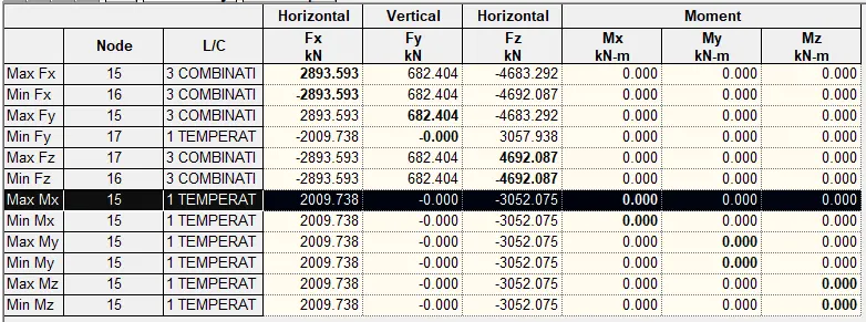
Figure Maximum reaction coming out of all the load cases
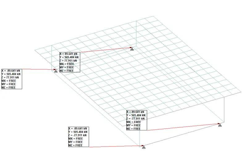
4. BEAM RESULTS:-
|
Mz (KN-m) |
My (KN-m) | Shear y (KN) | Shear Z (KN) |
| 251.360 | 103.094 | 344.520 | 172.250 |

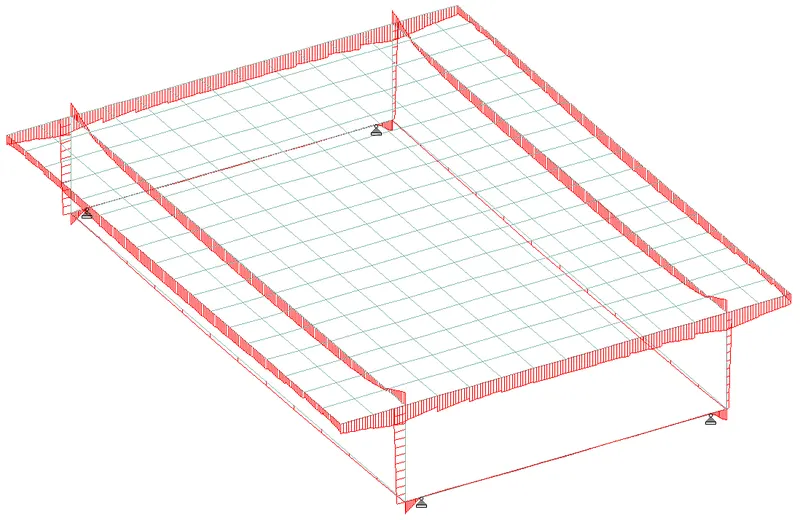
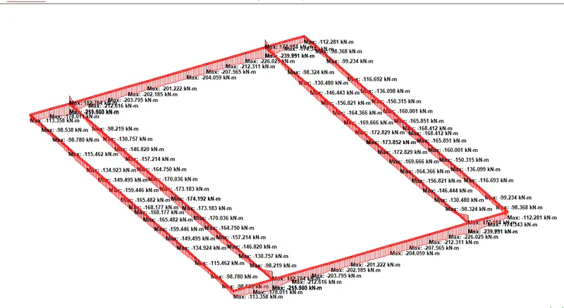
Figure Bending moment diagram of box girder bridge
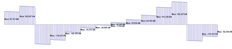
Figure Shear force diagram
VERTICAL BEAM MEMBER RESULTS OF BOX GIRDER
|
Mz (KN-m) |
My (KN-m) | Shear y (KN) | Shear Z (KN) |
| 115.434 | 11 | 30.521 | 13.773 |
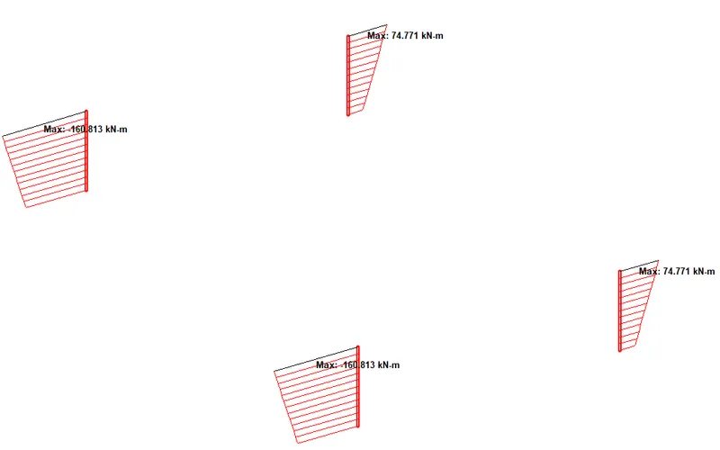
Figure Bending Moment
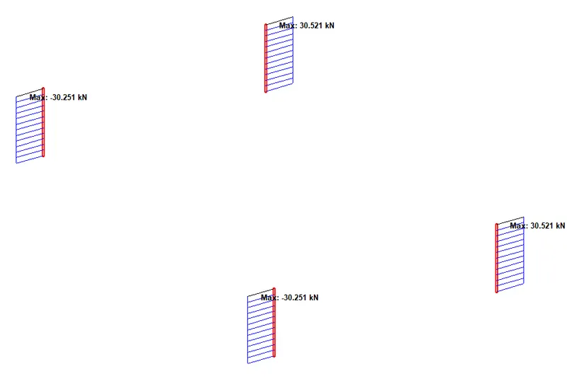
Figure Shear Force
5. PLATE STRESSES
Deck slab
|
Mx (KN-m/m) |
My (KN-m/m) | Mxy (KN-m/m) | Shear X (N/mm2) | Shear Y (N/mm2) |
|
26.882 |
62.707 | 188.722 | 0.525 | 0570 |
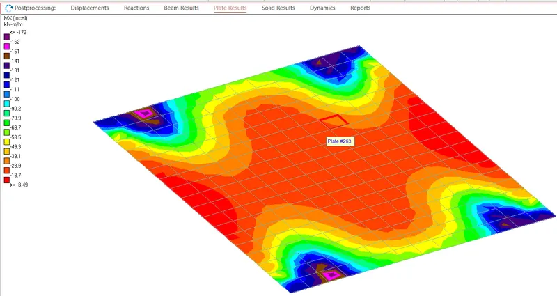
Figure Plate stresses
BOX GIRDER BASE PLATE STRESSES
|
Mx (KN-m/m) |
My (KN-m/m) | Mxy (KN-m/m) | Shear y (N/mm2) | Shear Z (N/mm2) |
|
11.837 |
179.121 | 0 | 0 | 0 |