Week 11 Challenge
AIM:
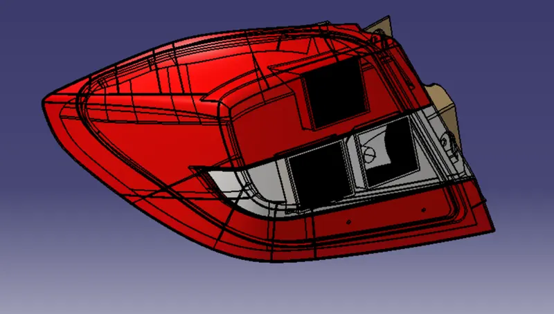
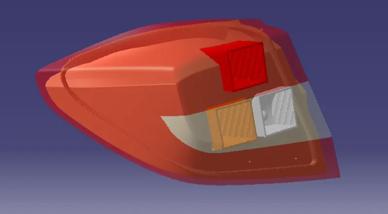
Create tail light assembly (lens, reflector, housing and slandered parts) from given class A surface. Then crate single part and assembly drawing for this light and check the regulation requirement for tail lamp.
INTRODUCTION:
LIGHTING:
Lighting is the deliberate use of light to achieve practical or aesthetic effects.
Automotive lighting system:
A vehicle has lighting and signalling devices mounted to or integrated into its front, rear, sides, and, in some cases, top. The devices illuminate the road ahead for the driver and increase the vehicle's visibility, allowing other drivers and pedestrians to see its presence, position, size, direction of travel, and its driver's intentions. In automotive lighting system different type lights are available such as head light, tail light, side indicator, stop lamp, reverse lamp, fog lamp, DRL(day time running lamp), cornering lamp, interior lamps.
Tail lighting system:
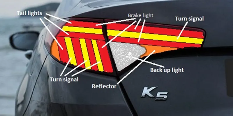
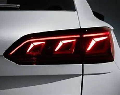
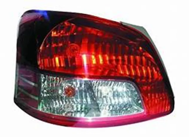
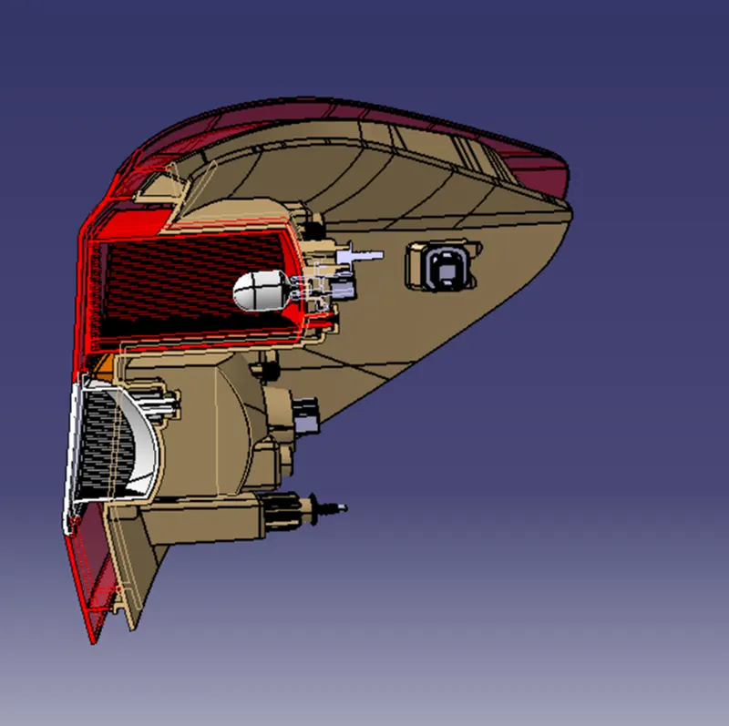
Tail lights are used to illuminate the rear of the car. Tail lights usually incorporate stop lights which flash red whenever the brakes are applied. Different types if lights are available such stop light, tail lamp, side indicator, fog lamp, reverse lamp, license plate lamp.
Reflector:
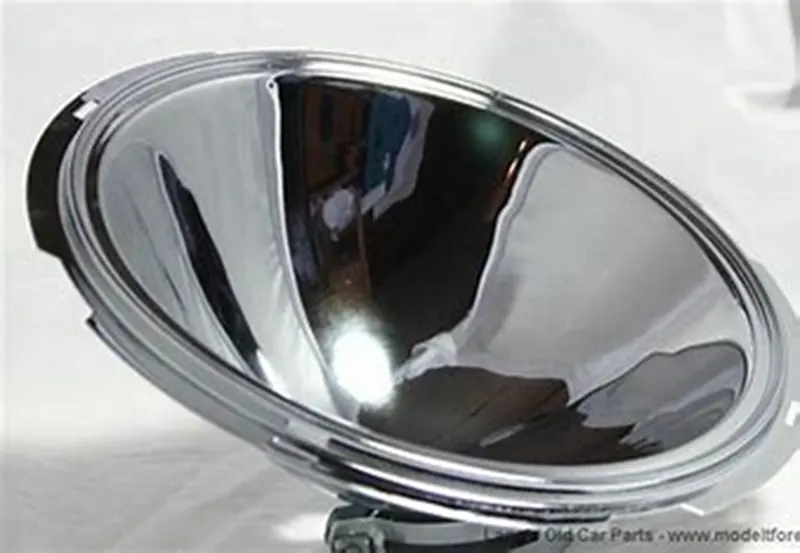
It is reflector surface which is project the light energy. It is in parboiled shape. In rear light three type of reflectors are there such as stop light, turn light and reverse light reflector. It is made by PMMA and BMC material.
Bulb:
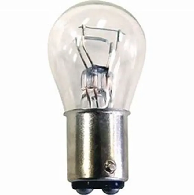
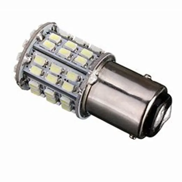
It gives light energy by current. It is fixed on the holder. In rear light three type of bulbs are there such as stop light, turn light and reverse light bulb. Stop bulb act as stop and back light function. Different types of bulbs are available such as halogen bulb, gas discharge and LEDs.
Lens:
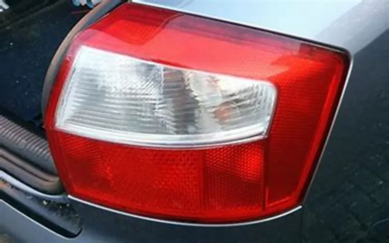
Lens is transparent which is transfer light from reflector lighting side to in front side. Then it acts as housing for bulb and reflector also. It is made by PMMA and PC. It is in different colour depend on colour.
Housing:
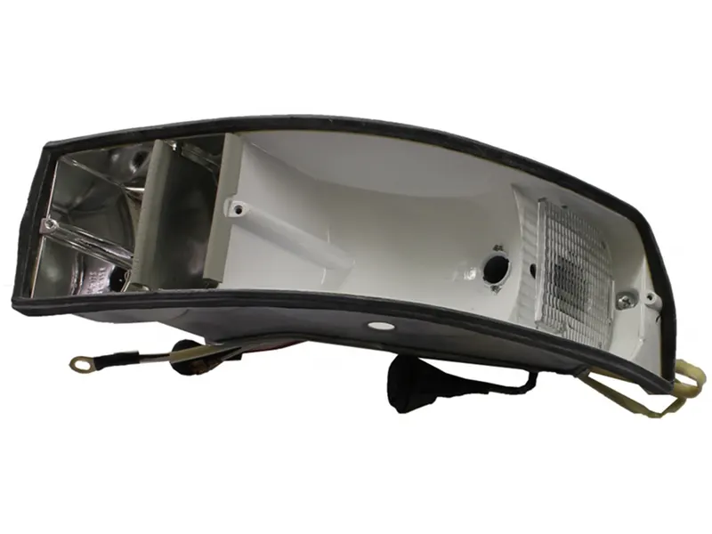
It is covering the reflector and wiring area of lighting. It joins with lens and product the full lighting system. All parts are fixing on this housing parts. Then it is fixed with BIW. It is made by PP plastics.
Standared parts:
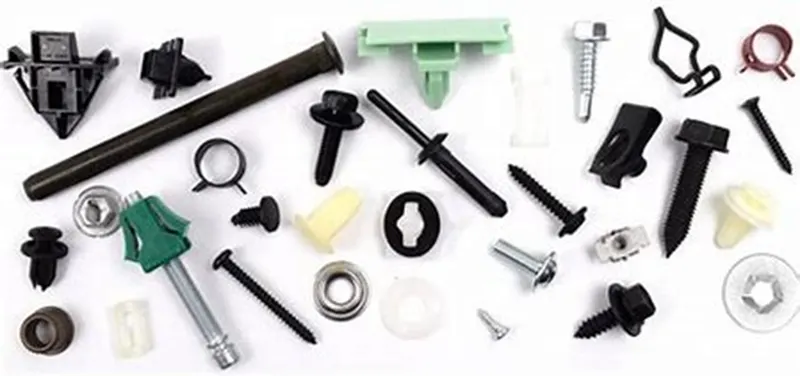
some standard parts are using to fix the light with BIW. Example fasteners, clips etc.
Wiring harness:
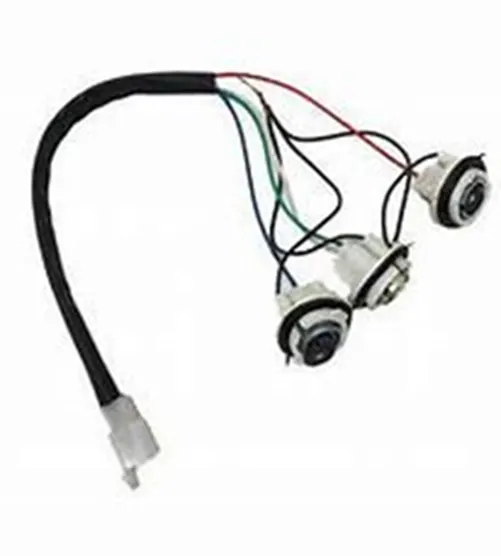
Wires are routing to lights from battery with the help of connector. The purpose of wiring harness transmits the electrical power or signal to a device.
CATIA:
It means Computer-Aided Three-Dimensional Interactive Application. It is computer aided designing software. This is software which is used to design 3D models with different workbenches.
CLASS A SURFACE:
It is surface which is made by the designer. It is aesthetic surface and usable outside futures are on this surface.
CLASS B SURFACE:
It is bottom side surface of class A surface. It is made by class A surface. It is formed with thickness distance from class A surface.
CLASS C SURFACE:
It joins the both class A and class B surfaces. This surface is equal to the thickness of the component.
TOOLING AXIS:
- Class A surface or part is used to manually analysis which is best for tooling and create the axis perpendicular to the product. It is called tooling axis. Mould is open and closed by this axis.
PARTING LINE:
- Core and cavity meeting line is called parting line.
DOG HOUSE:
It is used mainly for three functions.
- To eliminate the sink marks
- To lift the bosses for hight
- To give outside bosses from B surface
RIBS:
Ribs give strength to the model. It is made by some guidelines like draft, fillets etc.
BOSS:
It is used to assemble the two parts by fasteners.
TOOLS:
- Extract:
This comment is used to create the required surface again. Which means copy the surface again for next operations.
2. Un trim:
This tool is used to un trim the surface which means create the full surface of previous surface from current surface.
3. Trim:
This tool is used to cut and eliminate the unwanted surface.
4.Extrapolated:
This tool is used to increase the length of surface or area with the help of different option.
5.Offset:
It is used to create the same surface again in required distance.
6. Edge Fillet:
It is used to create sharp edges to round edges.
7. Boundary:
It is used to form the boundary lines on opened surface.
8. Sweep:
It is used to create the surface in required length from the profile.
9. Join:
It is used to join the separate surfaces and create the single surface.
10. Close (Part command)
It is used to create the solid part from closed hollow part.
11. Pad:
It is used to create the part body with the help of sketch with required dimension.
12. Pocket:
It is used to create the slot with the help of sketch with required dimension.
13. Thicken:
It is used to give thickness to the surfaced create the part body.
14. Boolean operations:
Union trim:
It is used to merge the two bodies and remove unwanted portion and keep the required portion.
Add:
It is used to add the two body and create a body.
Remove:
It is used to remove the unwanted portion with the help of another body.
Assemble:
It is used to assemble the two-part body. If it is in pad it will add. If it is is pocket it will remove.
- Edge fillets:
It is used to bled the sharp edges.
METHODOLOGY:
Light creation:
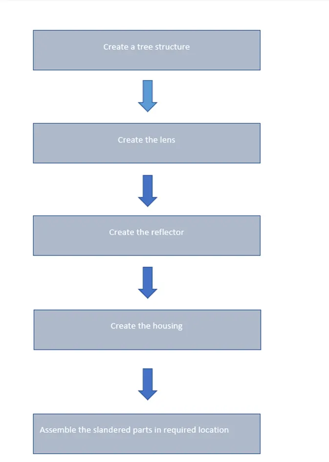
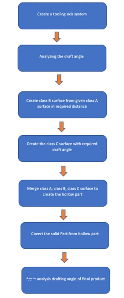
Part creation:
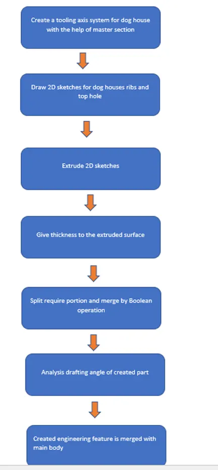
Engineering Feature:
DESIGNING:
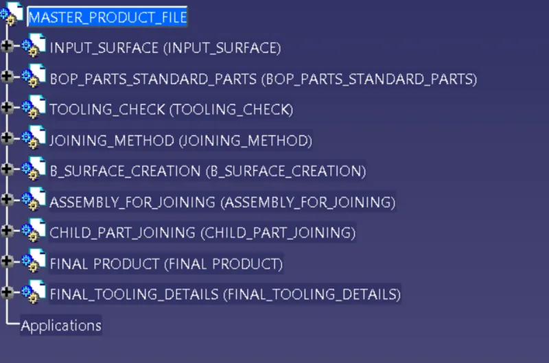
FOLDER CREATION:
First create assembly tree structure which is used create parts with appropriate name and finally take in final product.
SURFACE A CLASS:
TOOLING AXIS OR TOOLING DIRECTION CREATION:
- Tool moving direction is called tooling direction which means core and cavity are moving in one direction which is called tooling direction.
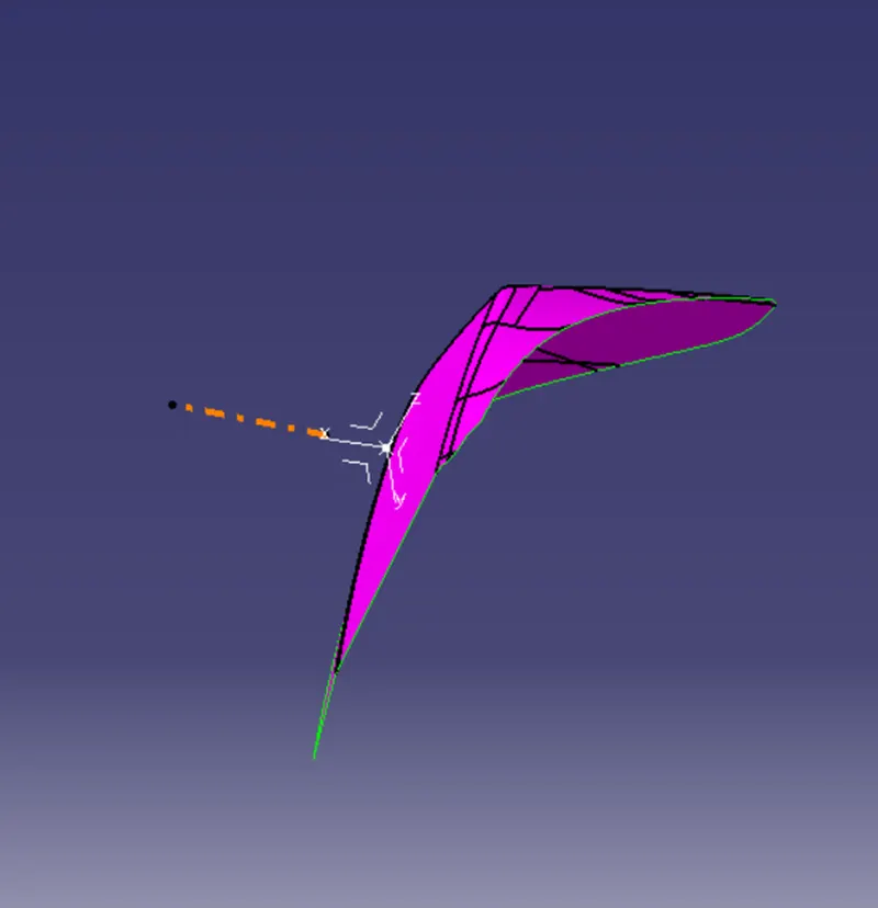
- Class A surface or part is used to manually create a axis and analysis by drafting analysis and change the angle and fix the correct tooling axis. It is best for tooling and create the axis perpendicular to the product. It is called tooling axis. Mould is open and closed by this axis.
- First take the class A surface and manually analysis and fix the direction of tooling.
- Carefully watch and take this axis with the help of all types of views.
- First create the point on the base surface. Then create a line and create another line and change the angle which is clear the drafting angle that line fixed as tooling direction with the help of drafting analysis.
- Change some appearance to this line like thickness, colour, dot lines. Finally, it is called tooling axis. It is published for frequent uses.
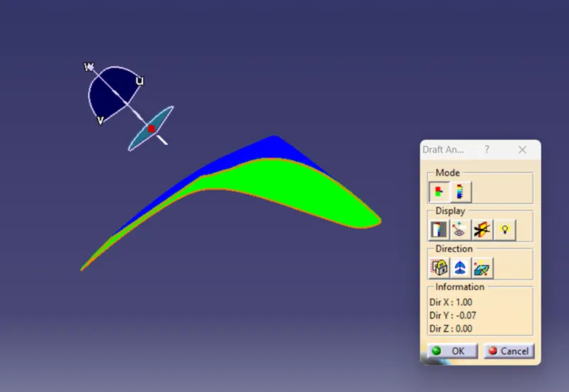
DRAFTING ANALYSIS:
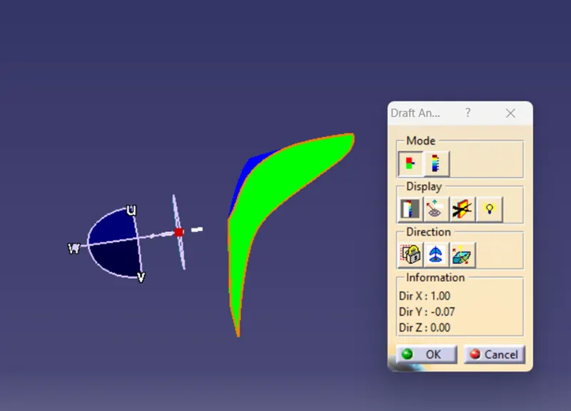
- Go to insert < analysis< feature draft analysis.
- Compass is fixed on the tooling axis.
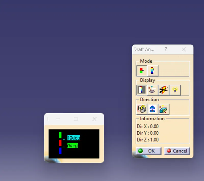
- Then we click on the surface it showing different colour. This colour is used to analysis the drafting value of surface with the help of analysis table.
- In this surface fully green colour by means which drafting value is grater then 10 deg. We also edit the table and colour to analysis the different drafting value.
SURFACE B CLASS CREATION:
Following procedures are used to create surface B class.
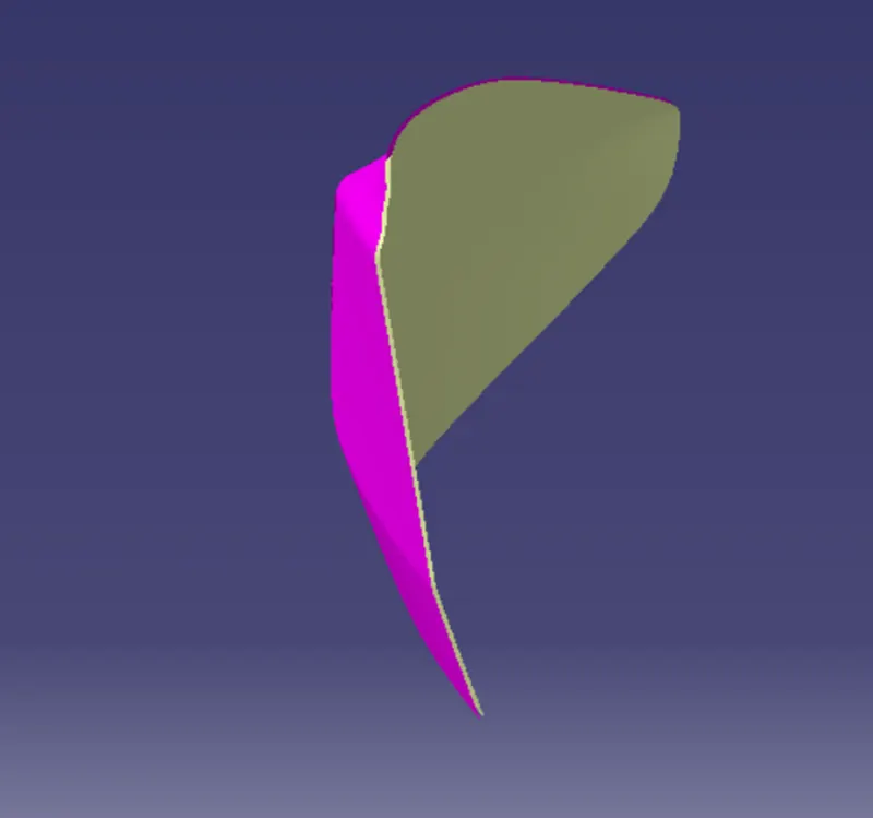
- Extract the input class A surface.
- Offset the surface 2.5 mm
- We got class B surface.
SURFACE C CLASS CREATION:
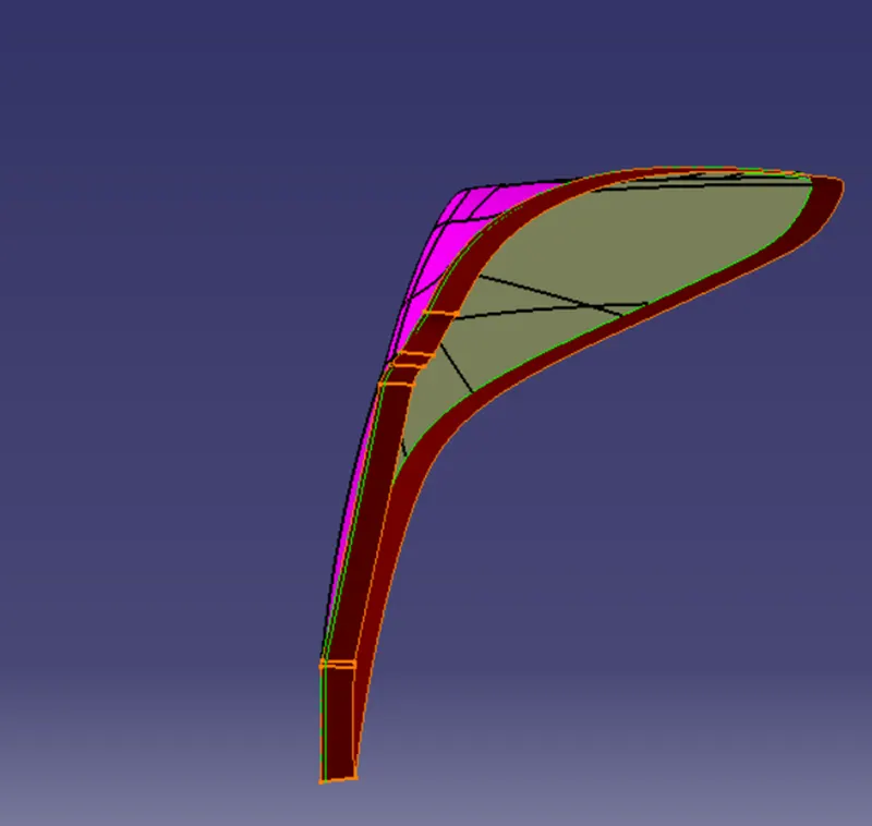
- It is created by boundary lines or extract edges to create surface. In this part extract file method was used.
- Extract the Class A edges. Smooth curve tool is used to change the smooth curves
- This curve is extracted by sweep command’s draft option.
FINAL LENS:
- Join command is used to join the surface A class and the surface B and C class. If the gaps are between two surfaces extrapolated commend is used extract and trim it. In this part it was followed. They Join themselves.
- Finally, we got hollow product. In part bench close commend is used to get the solid model
- It is again above drafting analysis process is used to analysis the drafting angle.
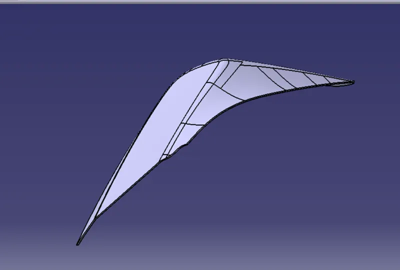
Housing also created by this method. Reflectors are created by thicken method.
DRAFTING ANYLYSIS:
Again, Same drafting analysis procedure is used to analysis the drafting angle of final part.
PARTING LINE CREATION:
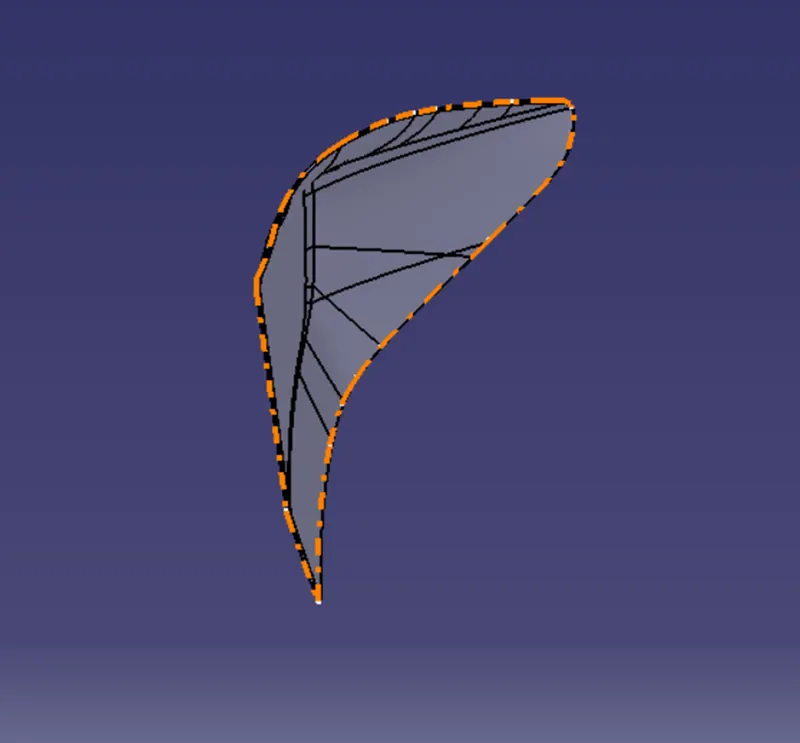
Where the core and cavity is meeting which line is called parting line. In this class A surface edge is parting line. So, extract the edge of the parting class A surface edge and created parting line.
Welding track creation:
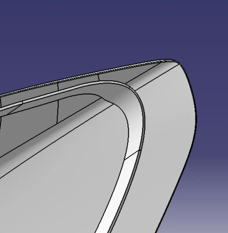
Create the welding track from lens. Create the ribs one the corner of lens.
Lense splitting:
Generally, two colours of lens for back light. Red lens is for stop function and clear lens is for turn indicator and reverse function.
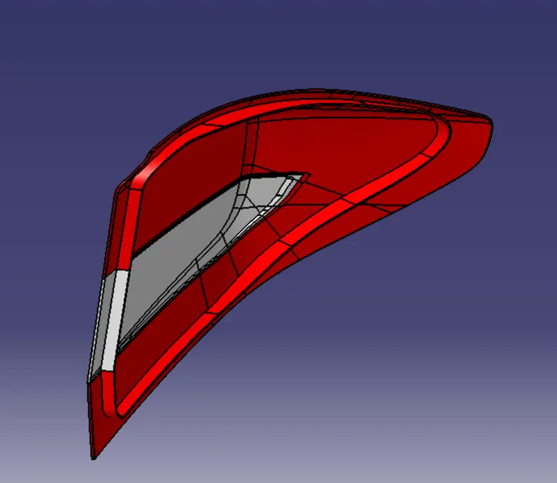
Create the surface and split the lens as two parts.
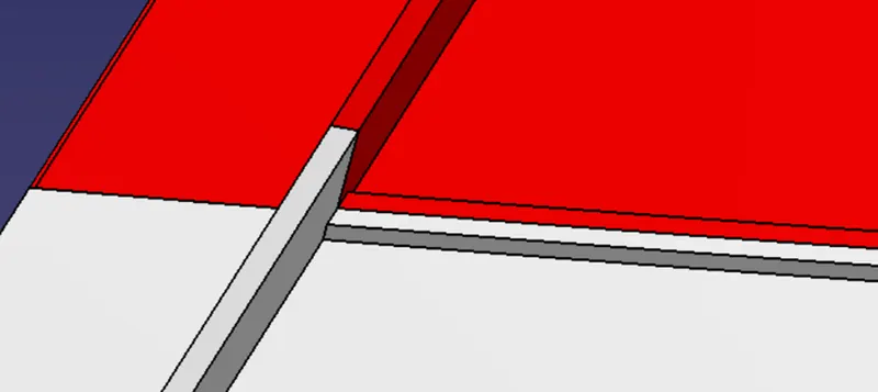
Then create the ribs on the side of the clear lens and create the slot on side of the red lens. This is used to assemble the clear and red lens.
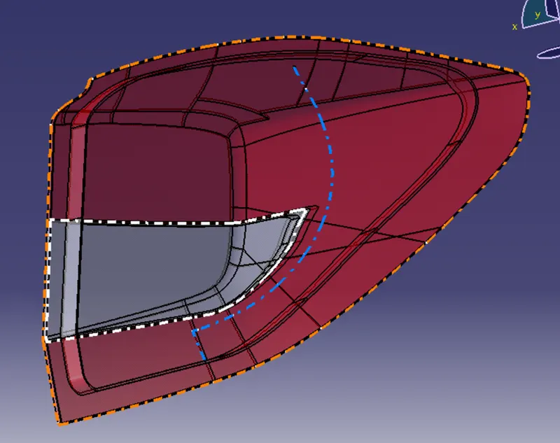
Parting line creation for undercut:
Parting line is created for lifter.
Reflector:
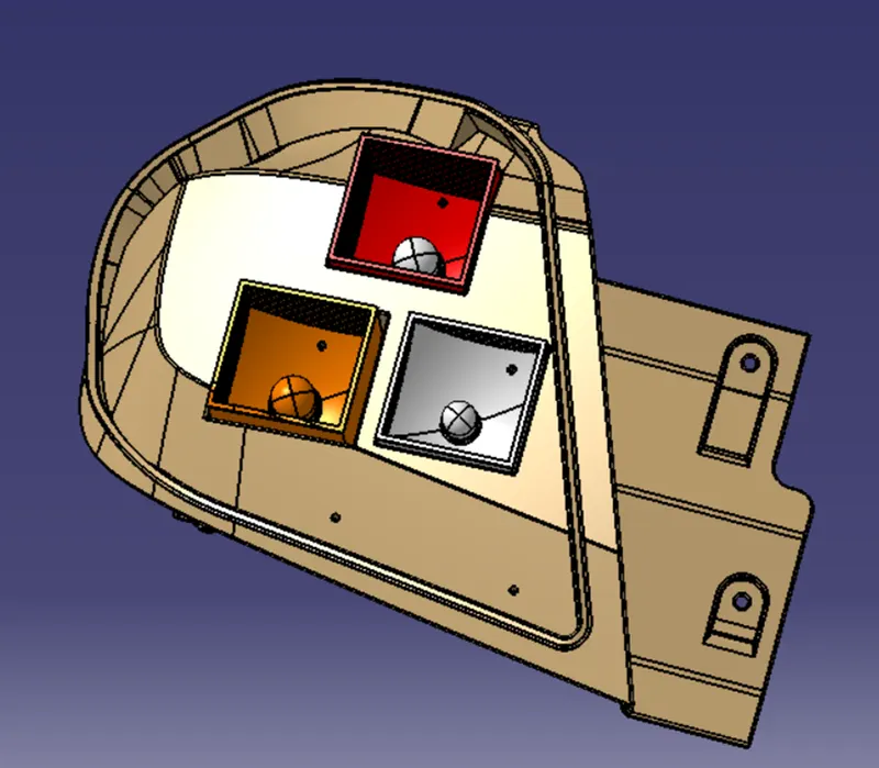
- First create the parabola then split with rectangular box.
- Then same lens class B creation method is used to create the solid for reflector.
- Three reflectors are created for stop, turn and reverse function.
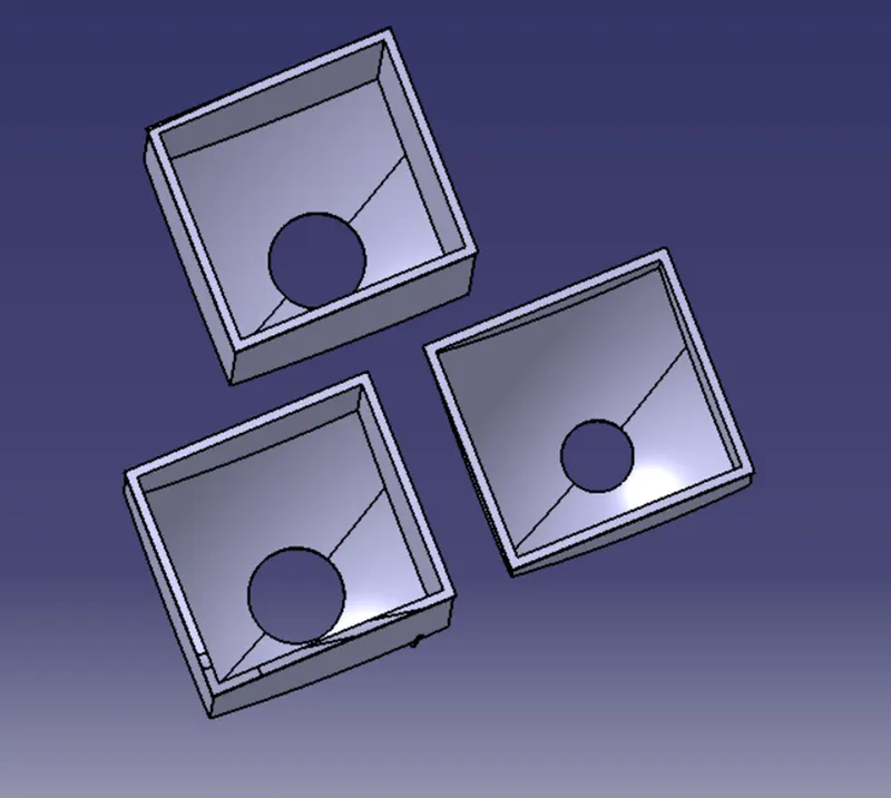
Boss creation to fix with housing:
Create the screw mounding boss with ribs to fix the reflector in the housing. In this part ribs act as locator also.
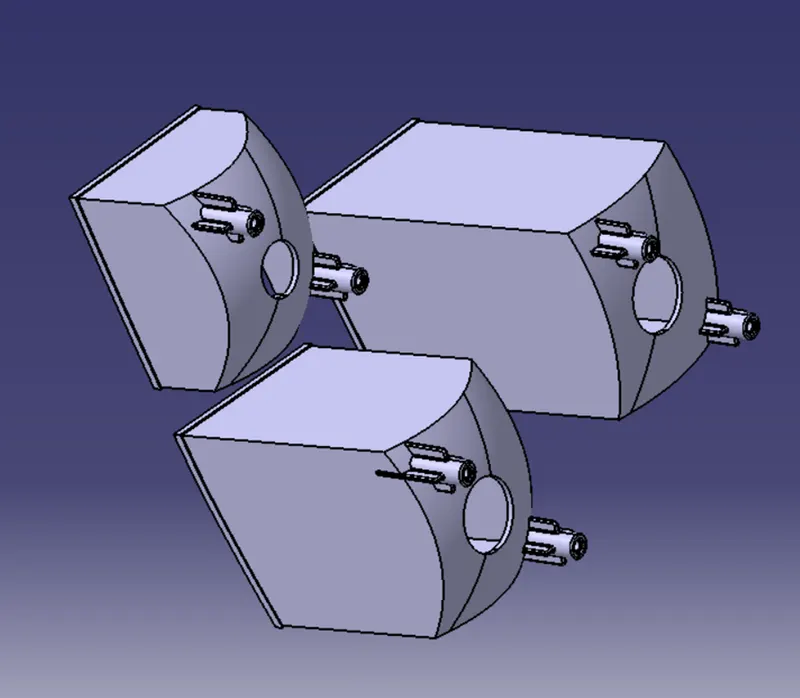
Vend hole creation:
When the lighting system is in process, heat is produced by light and it gives heat on reflectors. So, we have to give vend holes on the reflector.
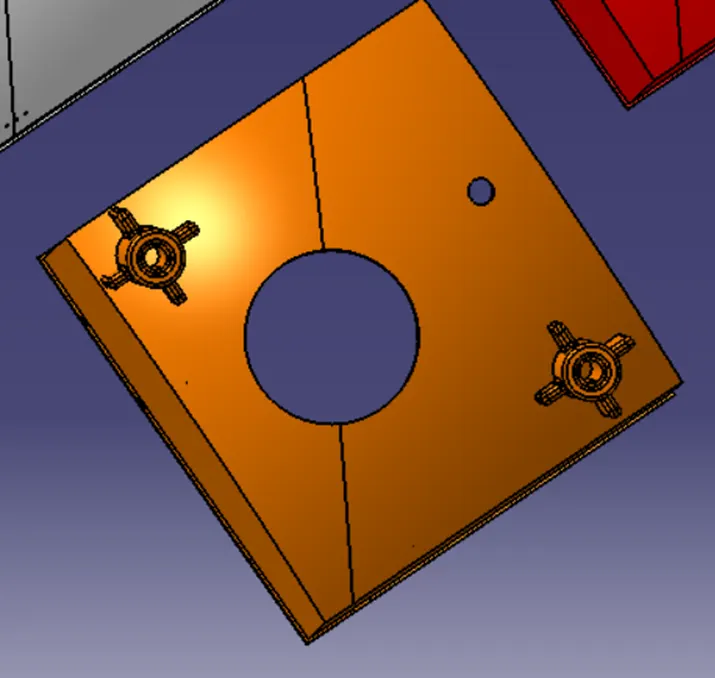
Flutes creation:
Flutes in multiple structure which is created on the lens and reflector. This gives uniform, increase the reflection, reduce the visibility of welding track. and give good aesthetics. And metallic coating also gives for reflection.
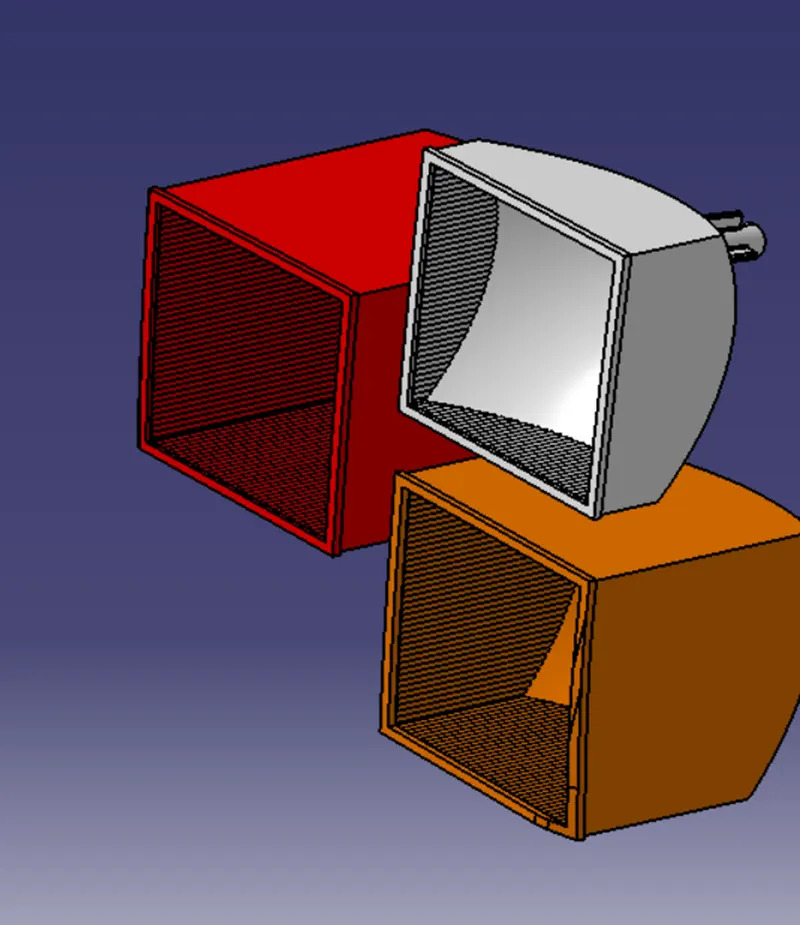
Create a flute and power copy is used to create the multiple flutes for three reflectors.
Housing:
Housing creation:
- First create the master section for housing.
- Then crate the surfaces by mater section
- Close the surfaces then create the solid.
- Create the welding track to weld with lens.
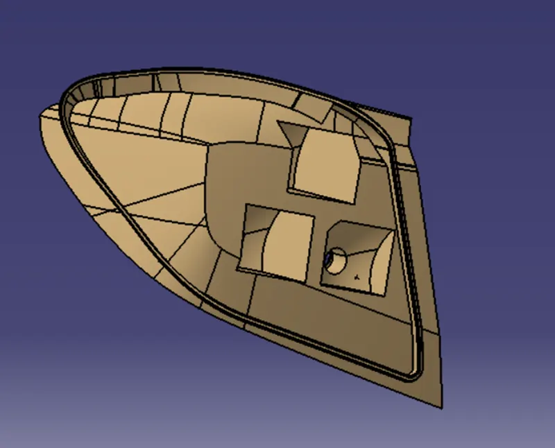
Reflector mounding boss creation:
Create the boss with ribs to mound the reflector with housing by M4 screw.
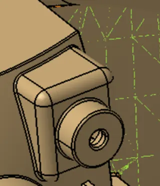
Dog house creation:
Dog house is created to increase the stud height for locking feature with BIW and to avoid the sink marks.
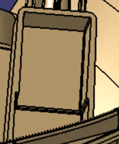
Locking feature creation:
Generally, three types of features are used to fix the housing with BIW such as stud with bolt, screw with washer, nut and clip.
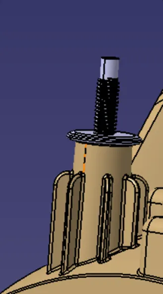
Create the boss with stud to fix the housing with BIW. And give ribs to give strength.
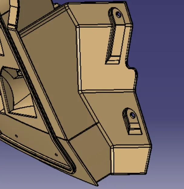
Then create the side flanges to screw the housing with BIW. Then give the ribs between flanges and housing to increase the strength.
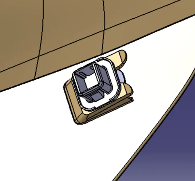
Then create clip mounding area to fix the BIW clip on this.
Vend hole boss creation:
We have to create the vent holes on the housing to out the heat from reflector vent holes. Additionally, give two vend holes on the downside of the housing to come the air into the housing.
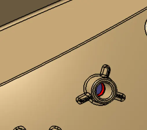
Create the boss with ribs for vend hole to fix the vent caps. In the part ribs act as vent cap holder and give the strength to bosses.
Wiring support creation:
Required wiring support is created to rout the wire for lighting
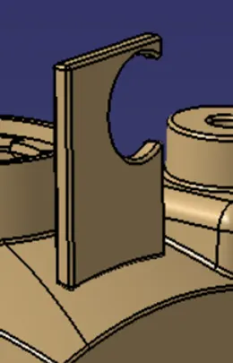
Dog house side core axis creation:
Create the dog house side core tooling axis.
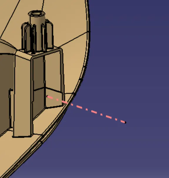
Ribs for reflector housing:
Some ribs are created in side of the reflector housing to increase the strength.
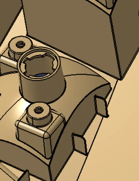
Filleting:
Required fillets are given on housing sharp edges.
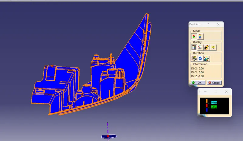
Draft analysis:
Analysis the drafting angle for housing. Where and all draft is needed have to give draft.
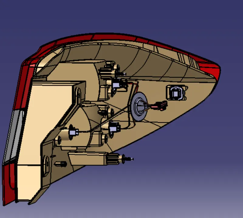
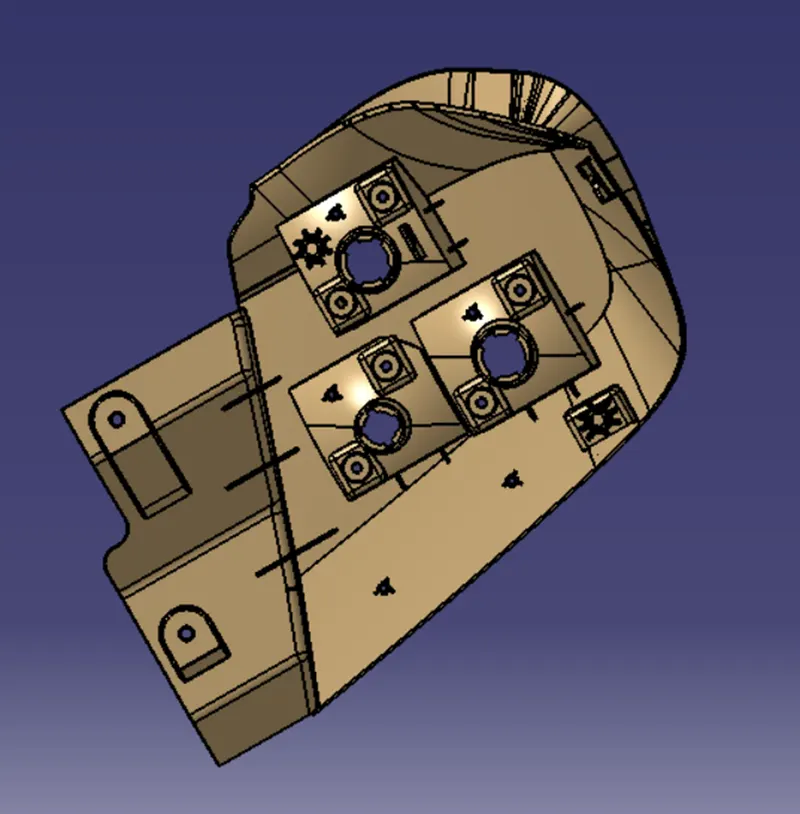
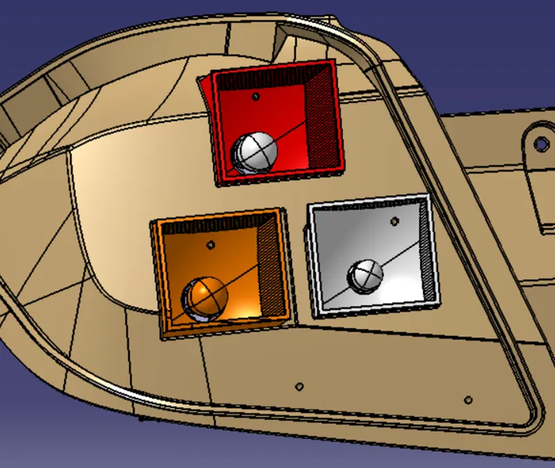
Bulb inserting:
Three types of slandered bulbs with holders are placed in appropriate location.
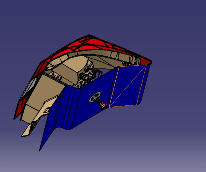
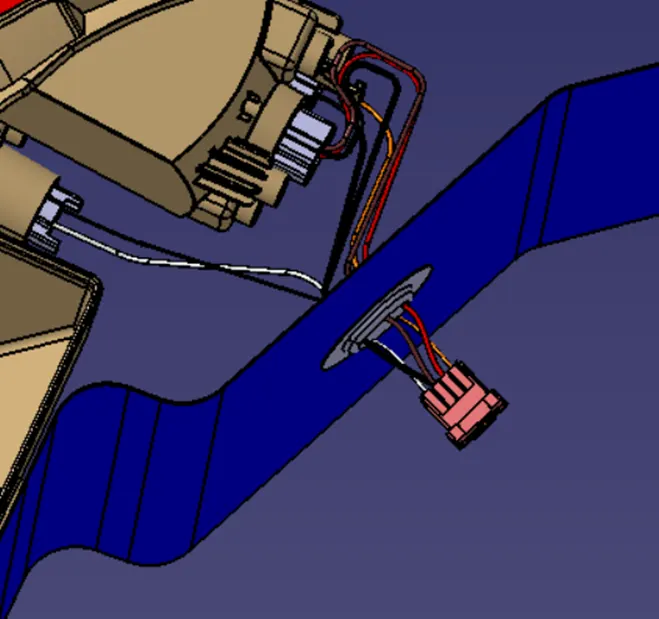
Wiring harness:
Create the grommets on the BIW to rout the wires from the connecter to lighting systems.
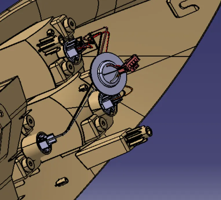
Then rout the wires from the connector to lights. Five types of wires are used such as black as grounding, red as stop light, brown as rear light, white as revers light and ambient as turn indicator light.
Regulation checking:
Check the regulation requirement with the help of 2D drawing.
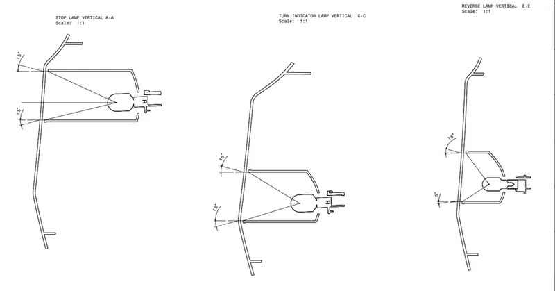
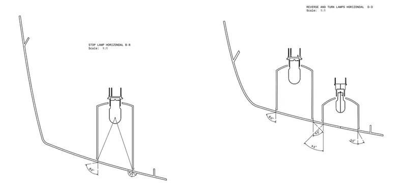
Then check the requirement height from the ground to reflector edges.
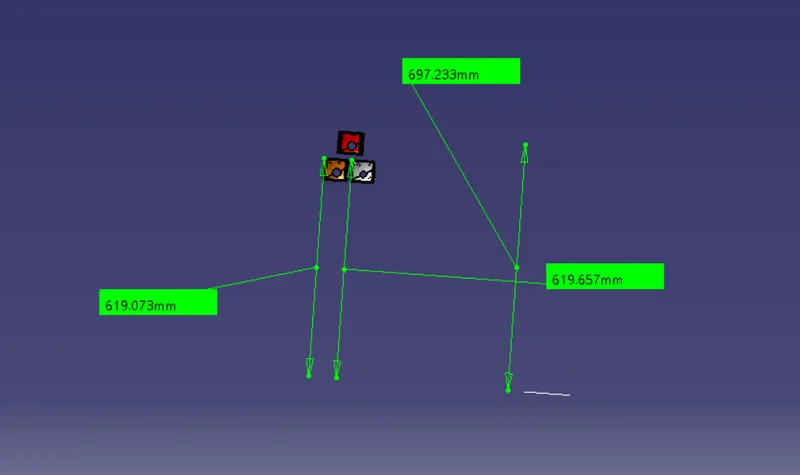
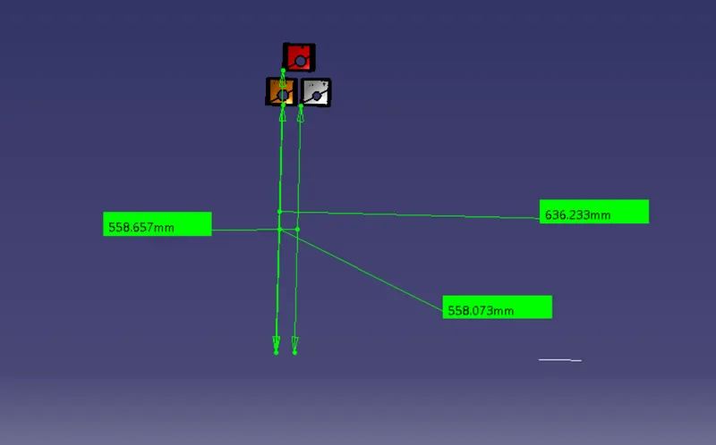
Light leakage checking:
2D drawing is used to check the light leakage or clashing between the stop and reverse or tail and turn indicator lights. If the light clashing happens, It will give different colour.
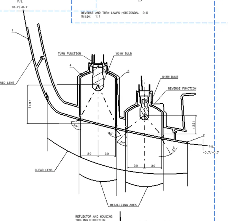
Check and give ribs in inside of the lens and extend the housing to reduce the leakages.
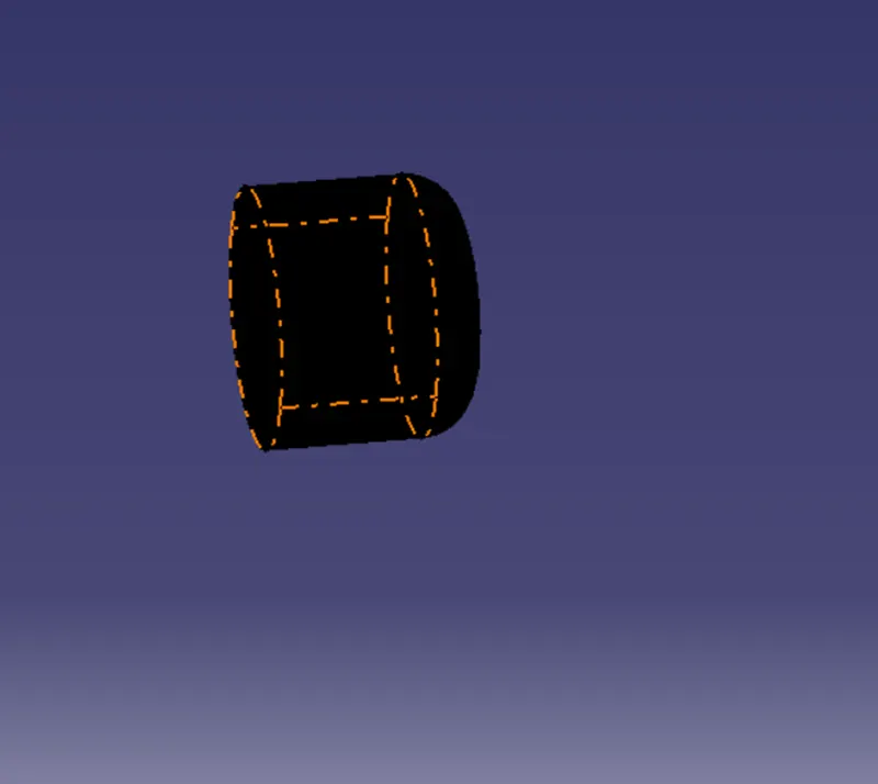
Vent caps creation:
If the vent hole is in open dust and moisture air is pass inside of the lighting system and affect light the system. So, we have to create the vend caps and close on vend hole boss. Five vend caps are used to close the all vend holes.
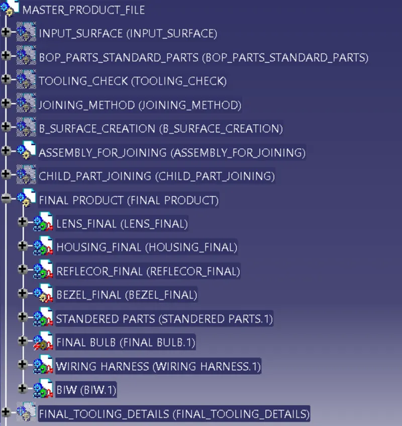
Arranging in the files:
Take the final products such as lens, housing, reflectors, wiring harness, bulbs and slandered part are placed in final folders with links. Parting line and tooling axis are put in final tooling details folder.
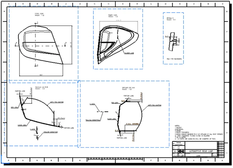
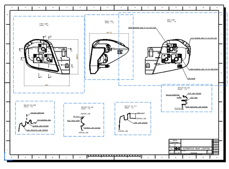
Drawing creation:
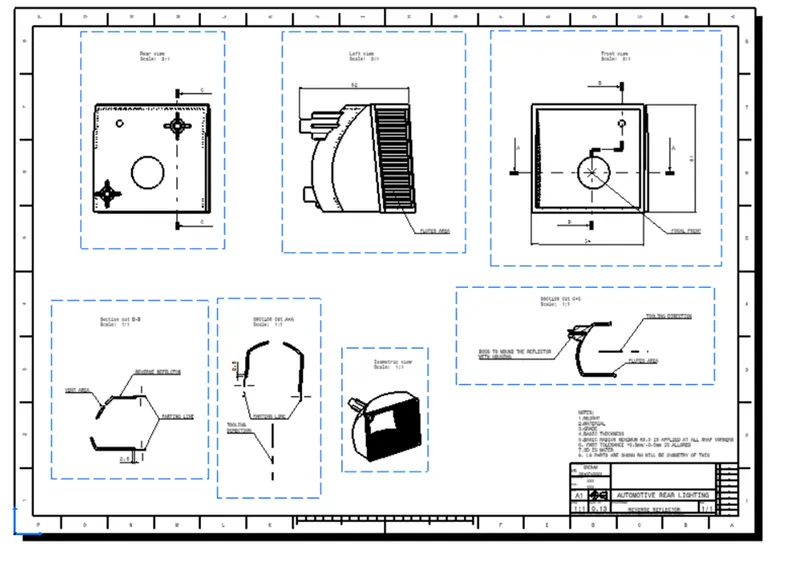
Single parts:
Detail drawings are created for three single parts such as lens, reflectors and housing.
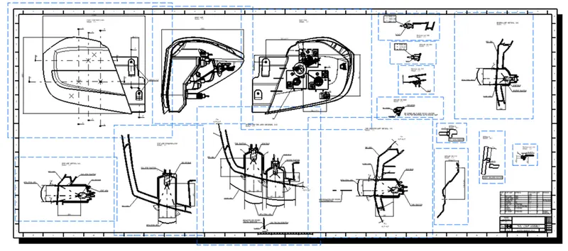
Assembly:
Detail drawings are created for full lighting system and mentioned the BOM detailes in drawing.
CONCLUSION:
Automotive rear light is successfully created with lens, reflector and housing and standard parts are assembled in the lighting system. Then detailed drawing successfully created and regulation requirement also checked.