Week 11 Car Crash simulation
OBJECTIVE
1. To simulate car crashes for different thicknesses of the car body,
- Case-1: Thickness=0.3 mm.
- Case-2: Thickness=0.5 mm.
- Case-3: Thickness=1 mm.
2. To find out Total deformation and Equivalent stress developed in the car body for each case and compare the results.
1. THEORY
1.1 Car Crash:
A crash simulation is a virtual recreation of a destructive crash test of a car using a computer simulation to examine the level of safety of the car and its occupants.
Crash simulations are used by automakers during computer-aided engineering (CAE) analysis for crashworthiness in the computer-aided design (CAD) process of modelling new cars. During a crash simulation, the kinetic energy, or energy of motion, that a vehicle has before the impact is transformed into deformation energy, mostly by plastic deformation (plasticity) of the car body material (Body in White), at the end of the impact.
Data obtained from a crash simulation indicate the capability of the car body to protect the vehicle occupants during a collision against injury. Important results are of the occupant space (driver, passengers) and the decelerations felt by them, which must fall below threshold values fixed in legal car safety regulations. To model real crash tests, today's crash simulations include virtual models of crash test dummies and passive safety devices (seat belts, airbags, shock-absorbing dashboards, etc.). Guide rail tests evaluate vehicle deceleration and rollover potential, as well as penetration of the barrier by vehicle.
Crash simulations are used to investigate the safety of the car occupants during impact on the front-end structure of the car in a frontal impact, the lateral structure of the car in a side collision, the rear-end structure of a car in a rear impact.
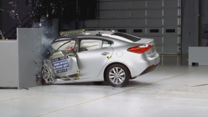
Fig. Frontal Impact
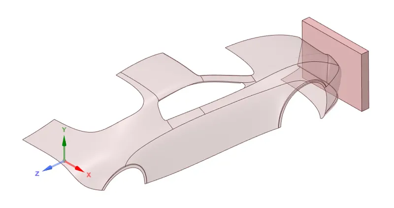
In this project, a car body is crashed against the wall. The wall is made to displace 500 mm, such that it gets crashed into the front portion of the car body and deforming the impacted region of the car body. A parametric study is carried out for different thicknesses of the car body, i.e., 0.3 mm, 0.5 mm and 0.7 mm. The results of total deformation and equivalent stress for different cases of car body thickness is compared and analysed.
2. STEPS FOR PERFORMING ANALYSIS:
1. Open ANSYS workbench.
2. Select the static structural module.
3. Select the proper Engineering data card.
4. Import geometry.
5. Open Mechanical model.
6. Give proper connections (contacts and joints).
7. Generate mesh.
8. Set Analysis Setting as given.
9. Insert output request
10. Analyze Result.
3. ANALYSIS SETUP:
3.1 Geometry:
The given 3D model of the car body and the wall is imported into SpaceClaim. The different thicknesses assigned for car body are as follows,
- Case-1: Thickness=0.3 mm.
- Case-2: Thickness=0.5 mm.
- Case-3: Thickness=1 mm.
3.2 Meshed Model:
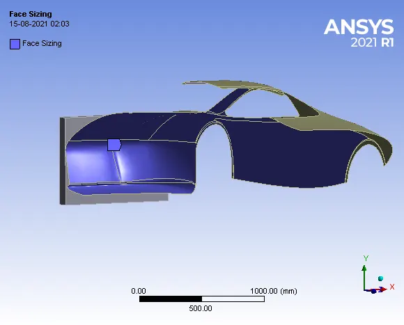
1. Face Sizing:
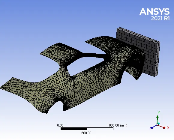
2. Meshed MOdel:
- Details:
- Face sizing = 40 mm
- Global Sizing = Default
- No of Nodes = 24093
- No of Elements = 46106
3.3 Material Properties:
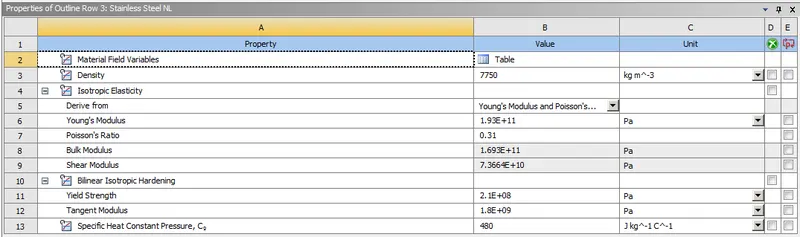
1. For Car Body: Stainless Steel NL
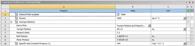
2. For Wall: Structural Steel
3.4 Symmetry Region:
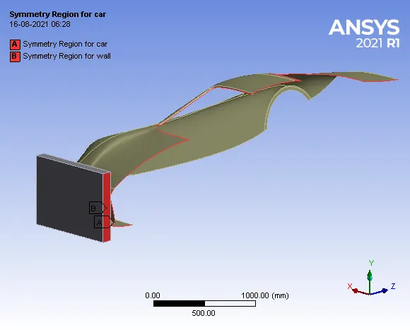
The given model is symmetric, hence only half a portion of the car body and the wall is considered for analysis to save computational time.
3.4. Analysis Setting:
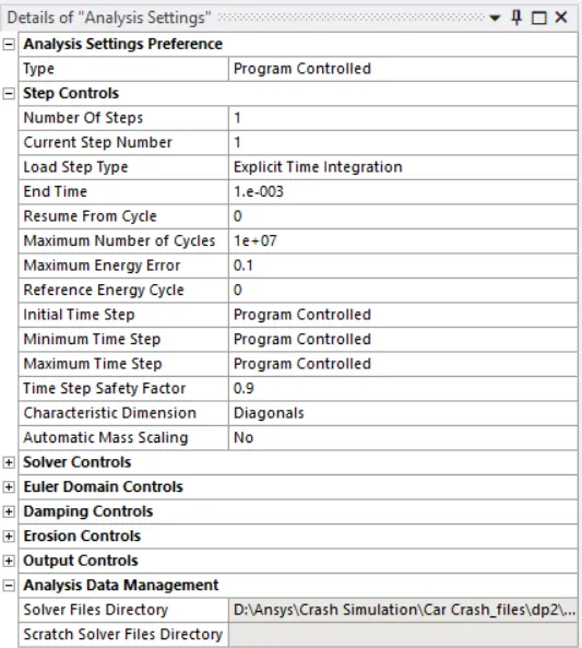
In the analysis settings, the number of steps considered is 1. The end time specified is 1e-003. The maximum no. of cycles is 1e+07. The maximum energy error is 0.1. The initial, minimum and maximum time step is set to ‘Program Controlled’.
3.5 BOUNDARY CONDITIONS:
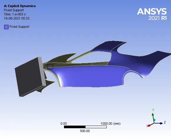
1. Fixed Support: The rear end surface of the car body is fixed.
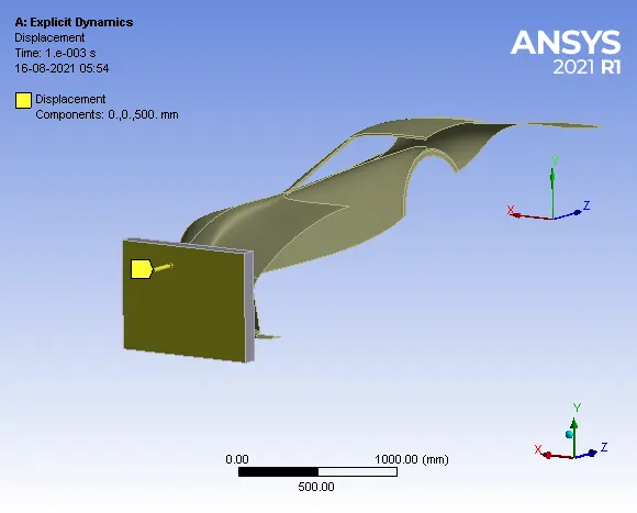
2. Displacement: The wall is directed to hit the front portion of the car body with a displacement of 500 mm in z-direction.
3.6 SOLUTION:
- After giving proper Boundary conditions, create a solution for the output result.
- Total Deformation of the model.
- Equivalent Stresses acting on the model.
4. Result and Discussions:
(A) CASE 1: Thickness 0.3 mm
1. Total Deformation:
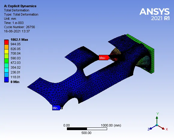
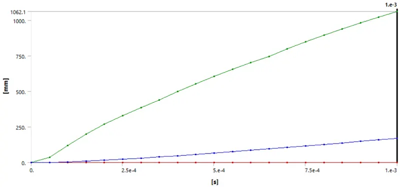
Maximum Deformation = 1062.1 mm
- Deformation Contours:
2. Equivalent v-m Stress:
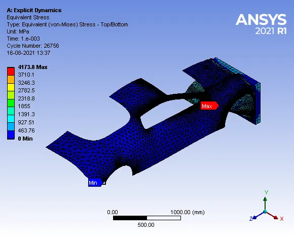
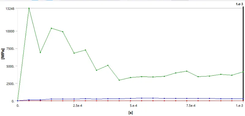
Maximum Stress = 4173.8 MPa
- Stress Contours:
(B) CASE 2: Thickness 0.5 mm
1. Total Deformation:
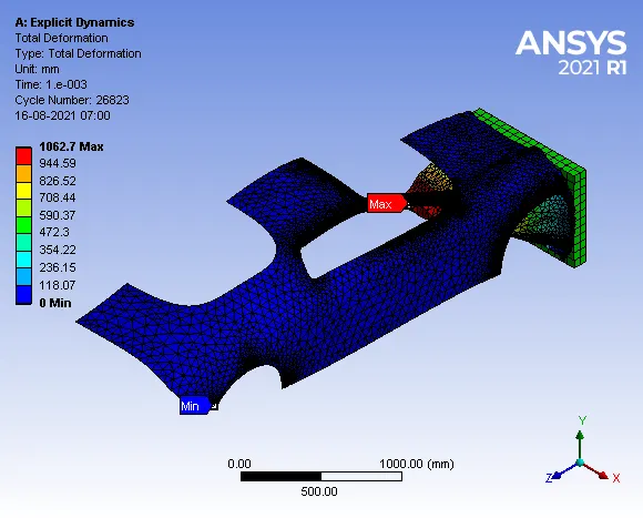
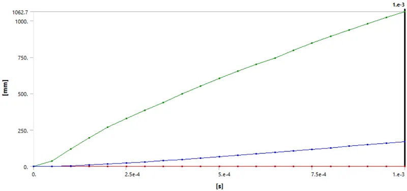
Maximum Deformation = 1062.7 mm
Deformation Contours:
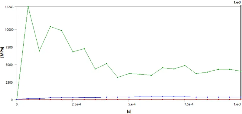
2. Equivalent v-m Stress:
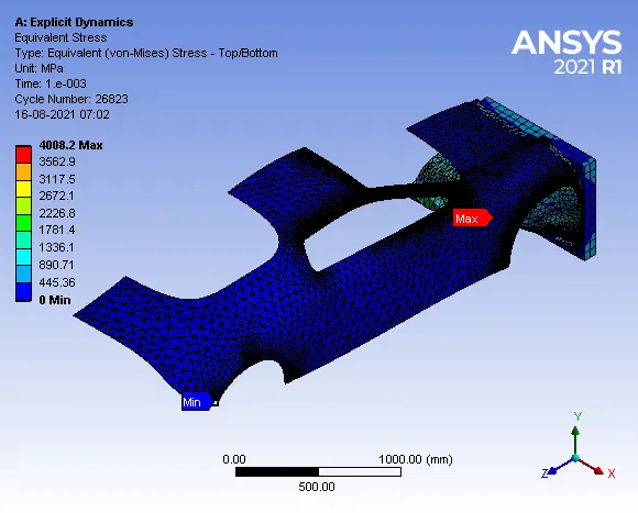
Maximum Stress = 4008.2 MPa
- Stress Contours:
(C) CASE 3: Thickness 0.7 mm
1. Total Deformation:
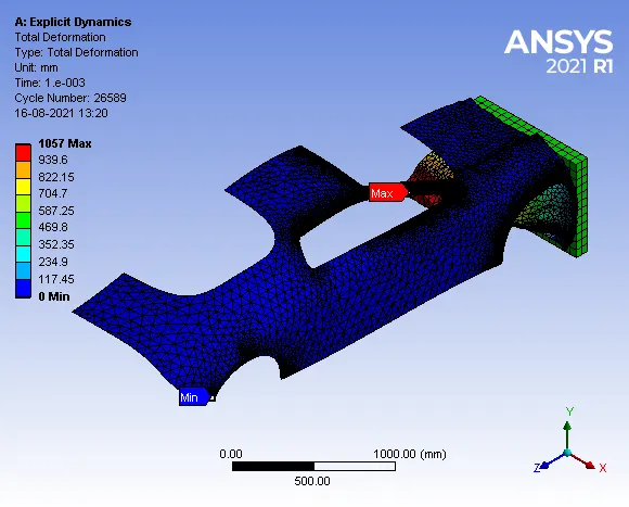
Maximum Deformation = 1057 mm
- Deformation Contours:
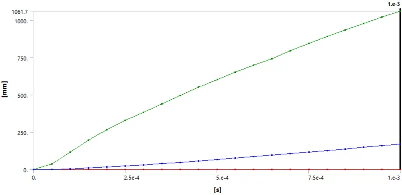
2. Equivalent v-m Stress:
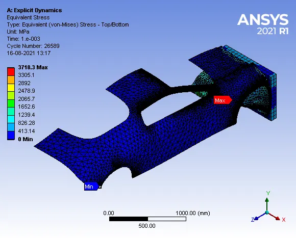
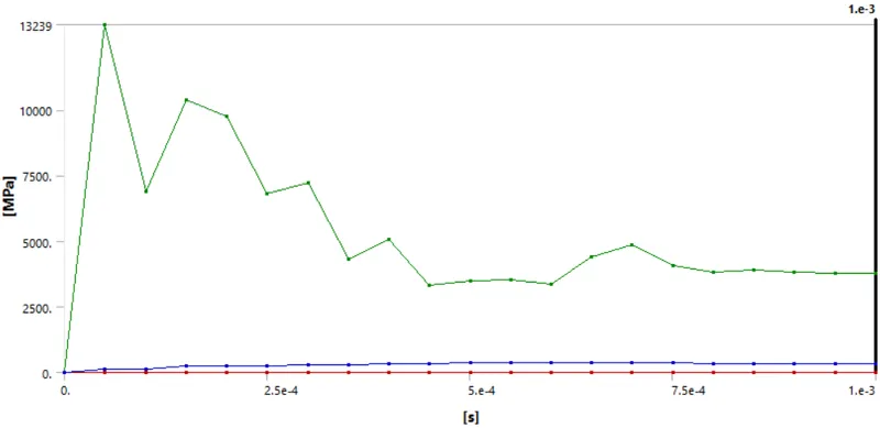
Maximum Stress = 3718.3 MPa
- Stress Contours:
5. Comparison Of Results:

From the table, it is observed that the maximum total deformation for case-1 and case 2 is almost same 1062.1 and 1062.7 mm which is more compared to case-3. The thickness of the car body for Case-1 and Case 2 is 0.3 and 0.5 mm, hence it gets deformed easily compared to case 3.
The v-m stress developed for case-1 is 4173.8 Mpa which is maximum compared to other cases because the stiffness is less and the impact forces absorbed in case-1 is more compared to other cases.
6. CONCLUSION:
Simulation of car body crashing the wall was carried out successfully for the following cases of car body thickness,
- Case-1: Thickness=0.3 mm.
- Case-2: Thickness=0.5 mm.
- Case-3: Thickness=1 mm.
The maximum total deformation for case-1 and case 2 is almost same.
The v-m stress developed for case-1 was maximum compared to other cases.
From the weight reduction point of view, case-1 is preferred, whereas, from the safety point of view case-3 is preferred.