Week 11 Car Crash simulation
Aim
1. To perform Car crash simulation using ANSYS Workbench
2. To perform a parameteric study using 3 different values of thickness of car body
Procedure
1. Geometry
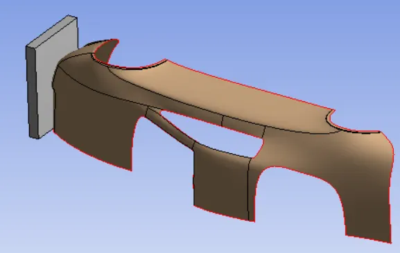
The geometry shown above is considered for car crash analysis. The brown colour sheet metal type part is car body and the Gray colour body is wall.
2. Symmetry Region
For the analysis we have defined two symmetry regions:
a) Wall Face
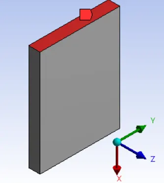
As shown above, wall upper face has been given a symmetry with the normal as X axis.
b) Car Body Edges
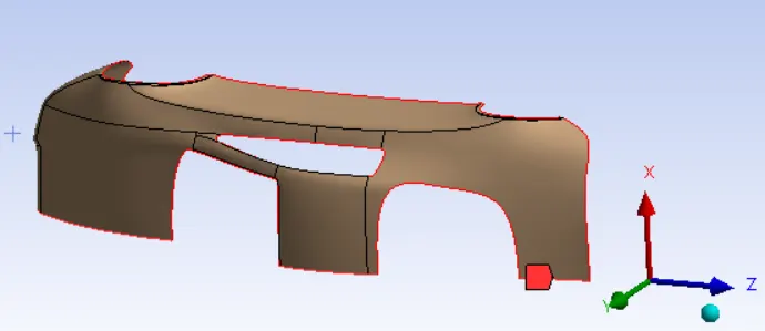
The lower edges of car body has been given as symmetry with X axis as normal.
3. Material Data
3.1 Structural Steel
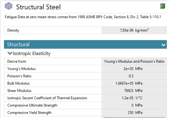
Wall is gven Structural Steel as material.
3.2 Stainless Steel NL
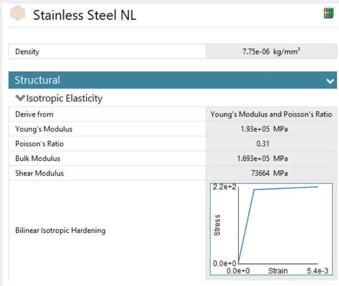
Car body is assigned by Stainless steel non linear material which has bilinear isotropic hardening as non linear characteristic.
4. Mesh
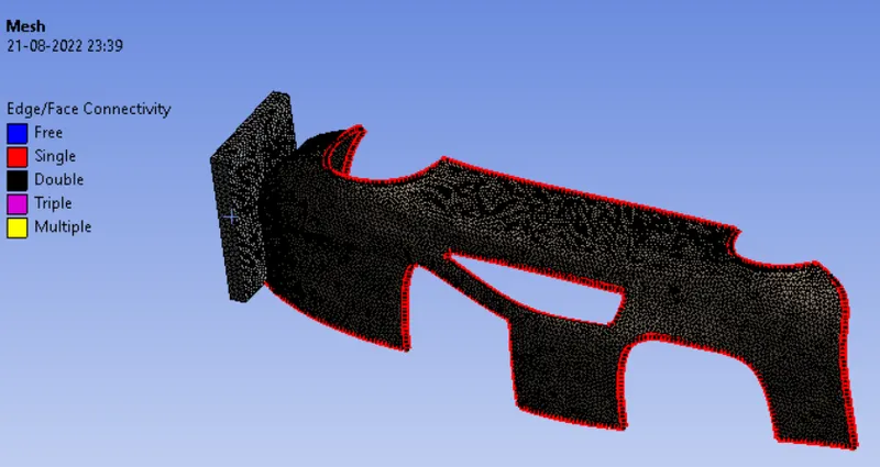
All the bodies were meshed using Tetrahedral Elements with element size as 25 mm.
5. Bounday Condition
The following faces of car body that are shown in the below image are fixed in analysis:
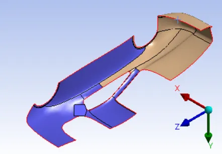
6. Load
Displacement
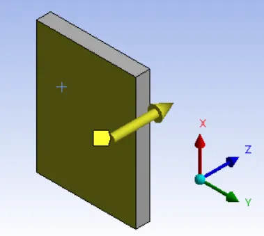
As shown above, the wall face has been given displacement of 500 mm in Z Direction to strike the car body.
7. Analysis Settings
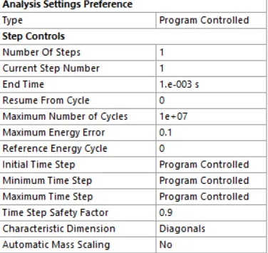
The following analysis settings has been used with end time as 10^-3 s.
8. Results
8.1 Thickness 0.3 mm
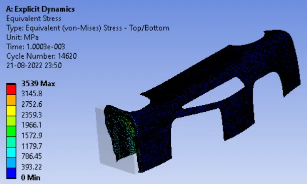
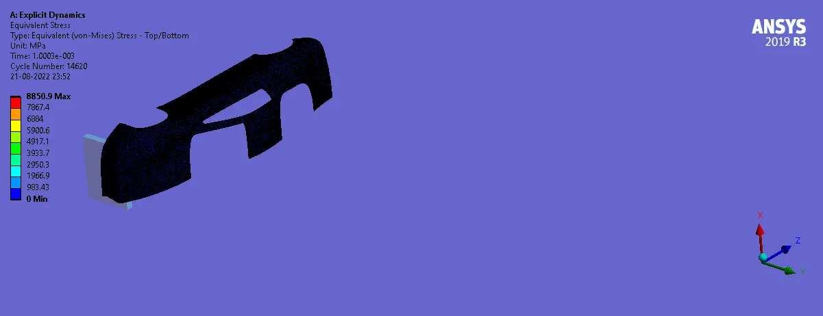
8.1.1 Equivalent Stress
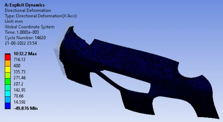
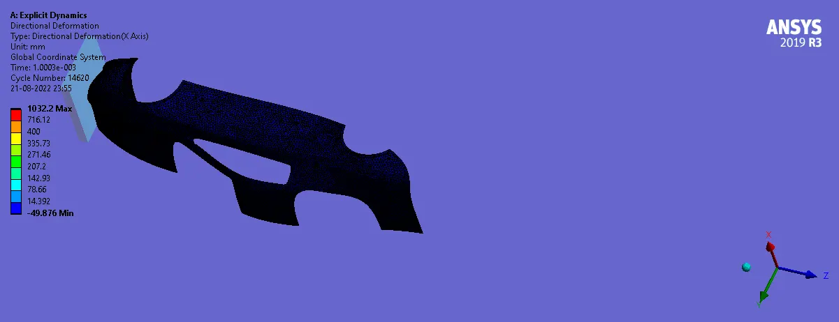
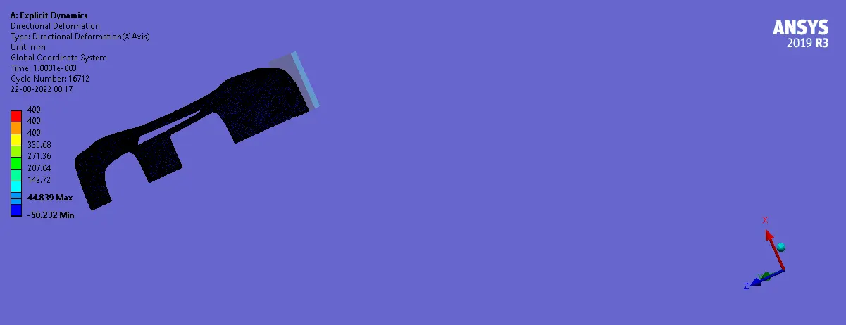
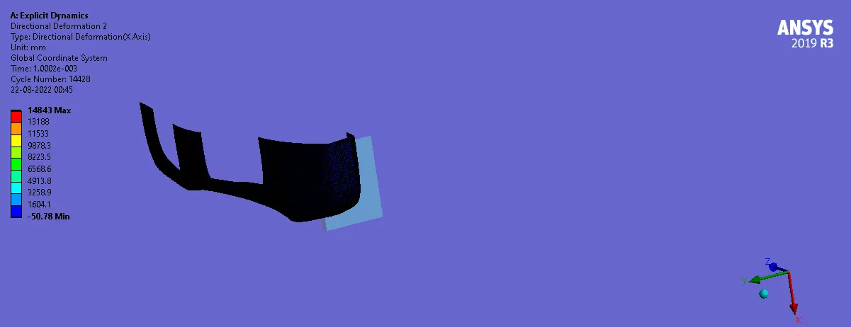
8.1.2 Directional Deformation
8.2 Thickness 0.5 mm
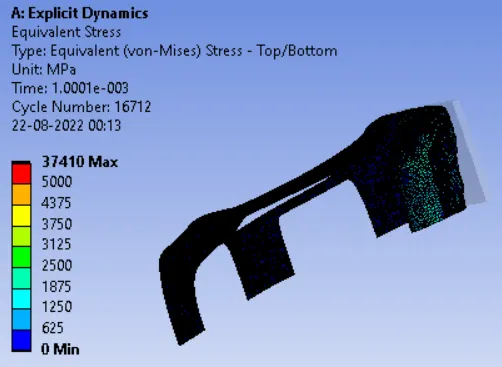
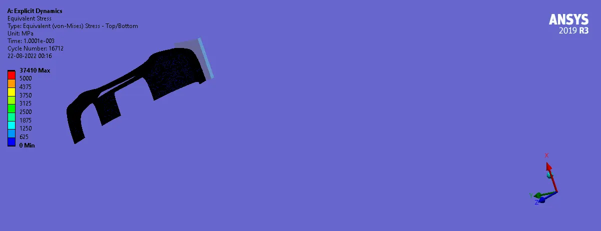
8.2.1 Equivalent Stress
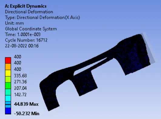
8.2.2 Directional Deformation
8.3 Thickness 0.7 mm
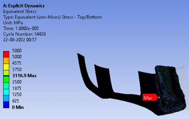
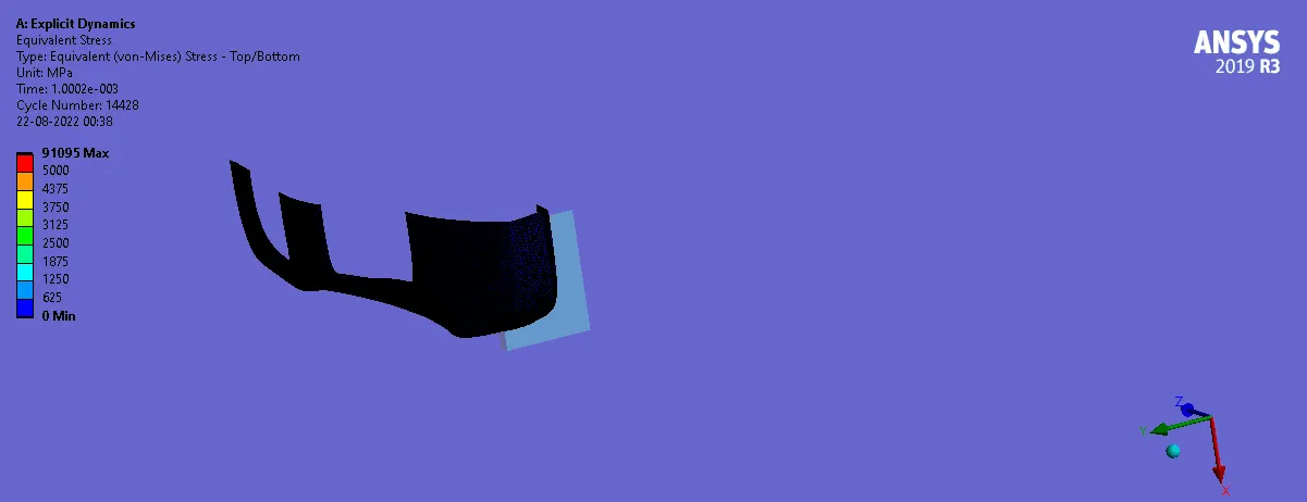
8.3.1 Equivalent Stress
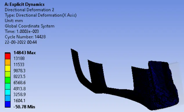
8.3.2 Directional Deformation
Conclusions
1. From the stress plots it can be observed that apart from stress singularity if we consider the increased thickness value then the average stress value has been decreased (ignore the max value which is on the one node only).
2. On the other hand, the deformation value in the carbody is also decreased with increased thickness as higher thickness make the car body more stiff.