Week 11 Car Crash simulation
Car crash simulation:
Aim: Performing parametric study on car crash simulation using three different values of thickness for the car body.
Steps followed:
1)Material selection:
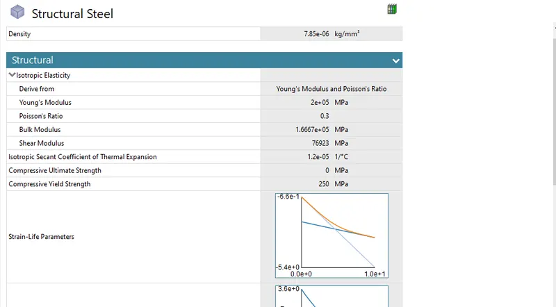
Wall is selected to be made up of Structural steel with material specifications as shown in the image below:

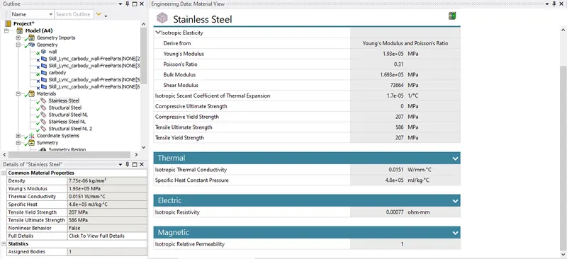
Car body is selected to be made up of Stainless steel with material specifications as shown in the image below:
2)Geometry:
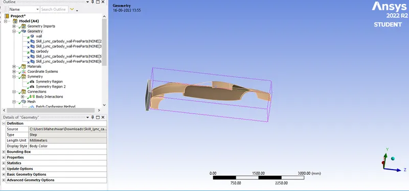
A CAD file of wall & car body assembly is imported and parts are renamed as Car body & Wall with thickness is taken as parameter for study of equivalent stress & total deformation as shown below:
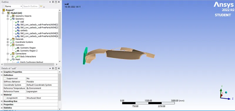
Wall is assigned with Structural steel as shown in the image below:
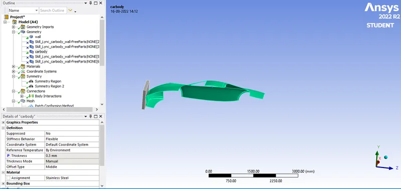
Case 1:
Car body is assigned with Stainless steel material & Parametric thickness of 0.3mm to the car body as shown in the image below:
Case 2:
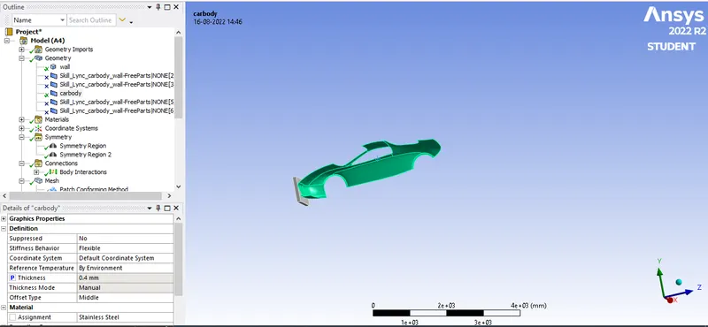
Car body is assigned with Stainless steel material & Parametric thickness of 0.4mm to the car body as shown in the image below:
Case 3:
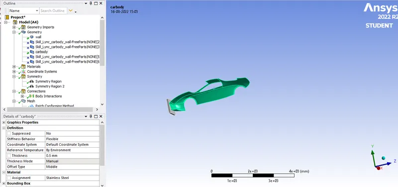
Car body is assigned with Stainless steel material & Parametric thickness of 0.5mm to the car body as shown in the image below:
3)Symmetry:
Two symmetric region is applied on the wall and Car body by selecting Model at the top & with right click selecting symmetry one for the wall face as shown below:
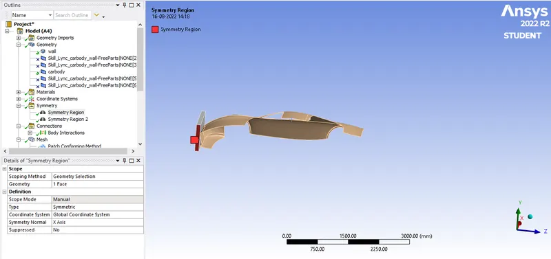
Another symmetric region is applied at the car body with the help of edge selection as shown in the image below:
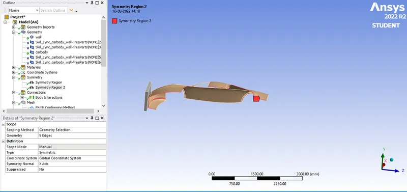
Symmetry for all three cases are similar.
5)Connections:
After clicking on connections delete all the contacts as we are doing crash analysis so contact is of no use to us here.
6)Meshing:
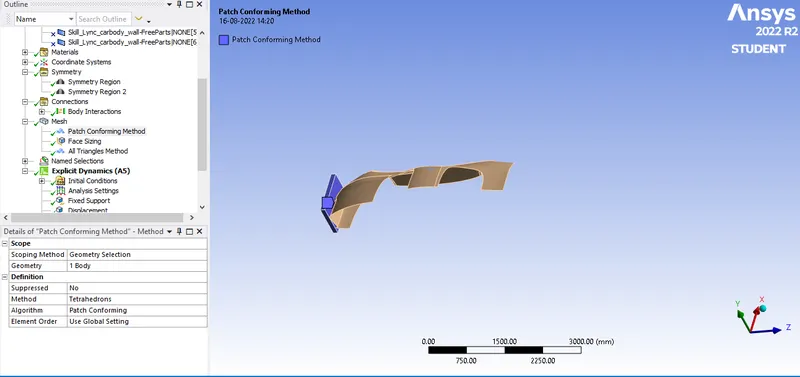
A Tetrahedron meshing is applied at the wall as shown in the image below:
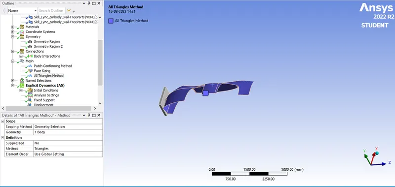
Entire car body is selected for Triangle mesh type with the help of Body selection as shown in the figure below:
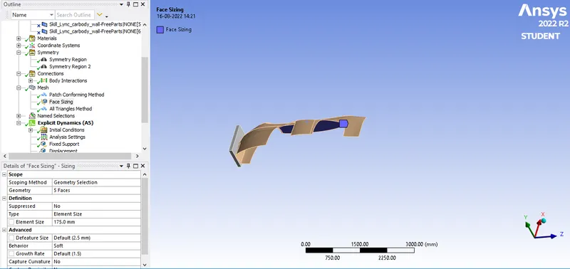
A Face sizing of 175 mm is applied to the faces of Car body which are not in contact with wall as shown in the image below:
A mesh of 25 mm size is generated as shown in the image below:
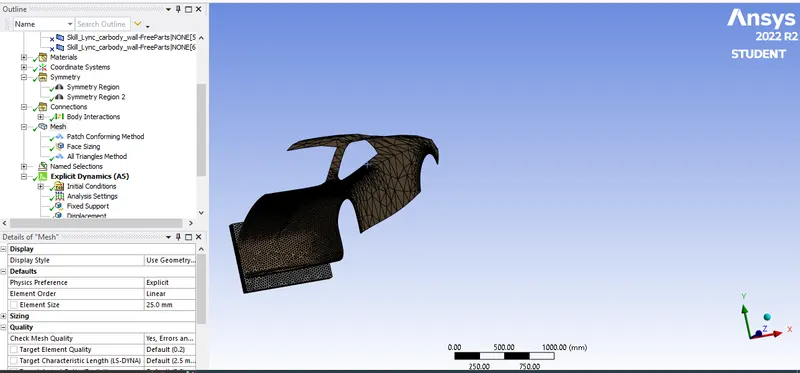
Mesh settings for all the three cases with their respective mesh sizing remains same.
7) Boundary candidtions:
a)Analysis settings:
Number of steps taken for analysis is 1 with End time as 0.001 s with Maximum energy error as 0.1 and Intial,Minimum & Maximum time step all as Programme Controlled as shown in the image below:
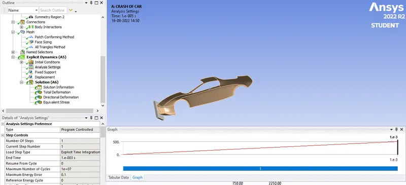
b)Fixed support:
Car body is kept fixed by applying fixed support to it by selecting the faces of car body not in contact with wall as shown in the image below:
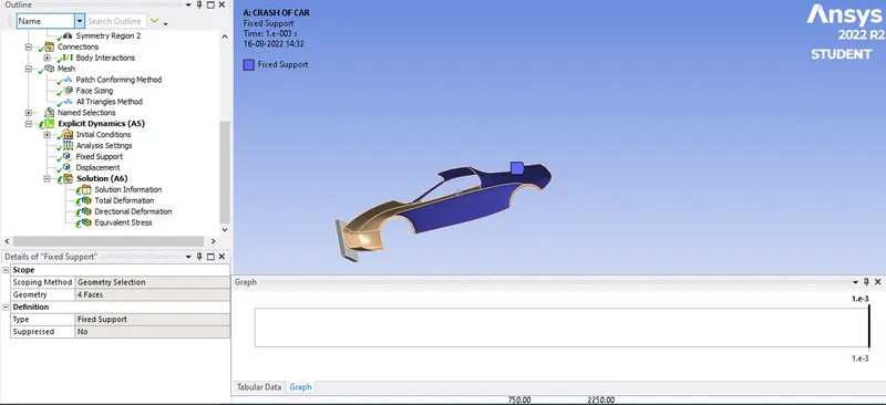
c)Displacement:
A displacement of 500 mm along Z axis is applied on the wall by selecting it's one face and kepping X & Y axis fixed as shown in the image below:
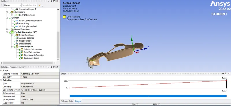
Boundary canditions for all three cases remains same.
Results:
Case 1: Car body thickness of 0.3mm.
Equivalent Stress:
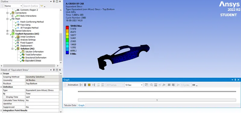
Equivalent Stress vs Time graph:
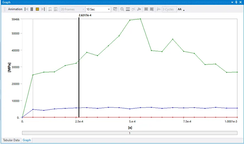
Maximum equivalent stress:58466MPa.
Total deformation:
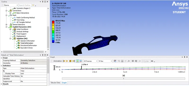
Total deformation vs Time graph:
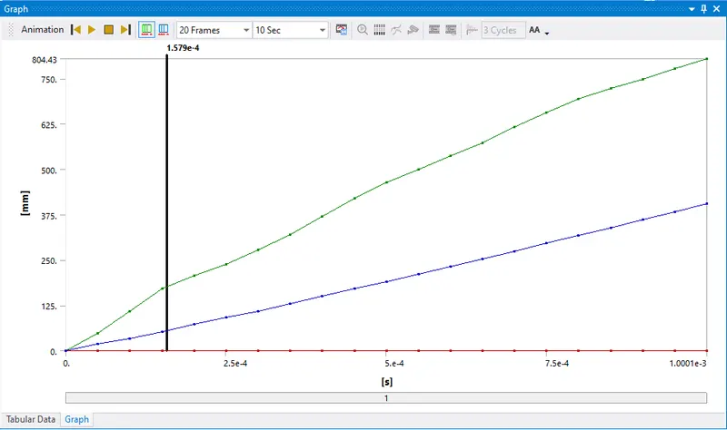
Maximum Total Deformation:854.94mm
Case 2: Car body thickness of 0.4mm.
Equivalent Stress:
Equivalent Stress vs Time graph:
Maximum equivalent stress:58466MPa.
Total deformation:
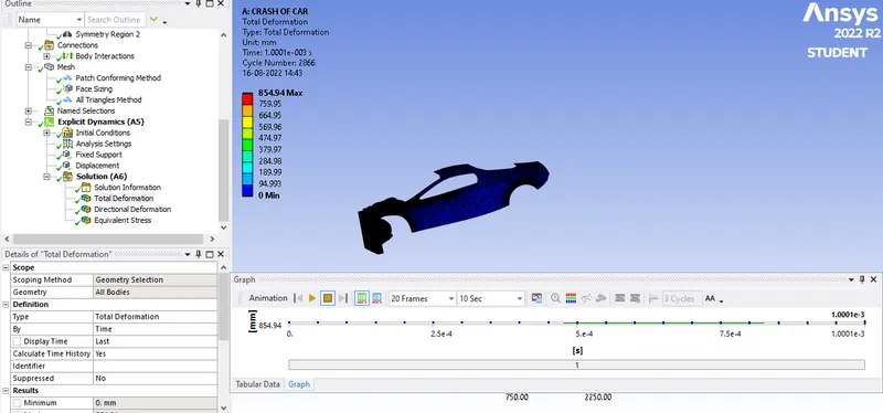
Total deformation vs Time graph:
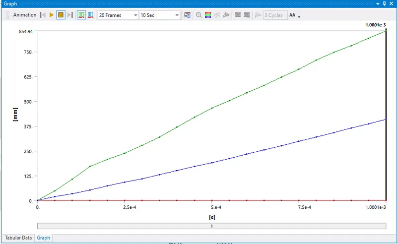
Maximum Total Deformation:854.94 mm
Case 3: Car body thickness of 0.5mm.
Equivalent Stress:
Equivalent Stress vs Time graph:
Maximum equivalent stress:58466 MPa
Total deformation:
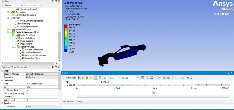
Total deformation vs Time graph:
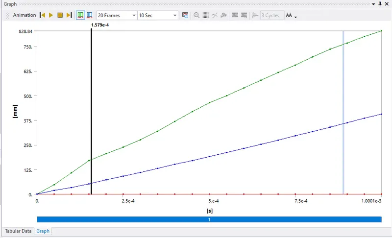
Maximum Total Deformation:828.84 mm
Comparision:
| Case | Maximum Total Deformation(mm) | Maximum Equivalent Stress(MPa) |
| 1 | 854.94 | 58466 |
| 2 | 854.94 | 58466 |
| 3 | 828.84 | 58466 |
Conclusion:
- It can be seen from the table above that,with the increase in thickness of car body maximum total deformation decreases because of high resistance offered by body with high thickness, thus highest maximum total deforrmation takes place in case of 0.3 &0.4 mm car body thickness.
- In order to resist the total deformation during crash, car body should be made with thicker materials.