Week 11- Broadband Noise modelling over Ahmed body
Introduction:
The Ahmed body is a geometric shape proposed by Ahmed and ram in 1984. The shape provides a model to study geometric effect on wakes of ground vehicles.
The Ahmed Body was first created by S.R. Ahmed in his research “Some Salient Features of the Time-Averaged Ground Vehicle Wake” in 1984. Since then, it has become a benchmark for aerodynamic simulation tools. The simple geometrical shape has a length of 1.044 meters, height of 0.288 meters, and a width of 0.389 meters. It also has 0.5-meter cylindrical legs attached to the bottom of the body and the rear surface has a slant that falls off at 40 degrees.
- Geometry:
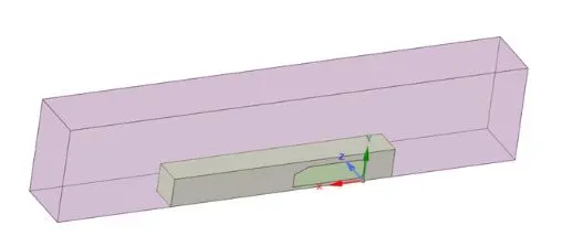
The model was imported to spaceclaim. The enclosure is provided to ensure that thge virtual wind tunnel like set up is created properly.
- Meshing:
The ideology followed here is:
- Prism layers are used near the walls. Since prism layers capture the boundary layer phenomenmon better.
- Tetra elements are used through out the domain.
- For body -
First cell height is determined , number of layers to be used is found out. The growth rate of the cells is 1.2
For the road, first aspect ratio is 5, num,ber of layers is 5 and the growth rate is 1.2
- Y-plus calculation:
Desired y+ value is 1.
- Free stream velocity is 31m/s.
- density of the flow is 1.225 kg/m^3
- viscosity of the material 1.8*10^-5
- Characteristic length is 3.7 *0.297
- Reynolds number= 227160 (Turbulent flow fully developed)
- First cell height = 0.01 mm
Pointwise y plus calculator is used.
This first cell height is practically the distance between the wall and the first grid point. (The characteristic length in most simple terms is the approximate length traversed by the flow over the body, for external flows. For internal flows, it is equal to the hydraulic diameter.)
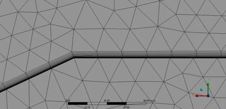
Mesh- Body sizing- inflation1-inflation2
Body sizing: The geometry selected is the whole domain. Then the body of influence is the density body. The elemnet size of the density body is 14 mm.
Infaltion1- The geometry selected is the density body. the boundary selected is the road.
inflation2: Multiple bodies are seleceted. Every part of the ahmed body is selected for creating the inflation layer. first cell height is selected as 0.01 mm and the number of layers is 28.
- Fluent set up:
1) Solver set up:
Pressure based solver is usd, since the mach number is really low. Here the main aim is to see the noise development in the last, so steady state simulation is performed.
2) Energy is turned on.
The viscous model selected is K omega sst model. production limiter uis turned on. The production limter takes into account for any erratic convergence issue.
3) Material selection:
The fluid is air. The solid is almuniuim.
4) Boundaty conditions:
- Inlet:
Velocity parameters are put into the inlet in component form. The x component of the inlet velocity is 31 m/s. Other parameters are kept as default.
- Outlet:
Pressure boundary conditions are prevalaent in the outlet. The default settingfs are went with.
- Road:
Moving wall type. The translation is the x direction is 31 m/s.All other boundary conditions are provided by default by fluent.
Refernce values:
The refernce values are computed from the inlet. The frontal area of the ahmed body is 0.10404 m^2
5) Solution controls:
Coupled approacxh is selected. The Courant number value is selected to be 10.
6) Report definitions:
Drag and lift coefficient are mionitored.
7) Convergence criterion:
The convergence criterion are set to default 1e-03.
8) Standard initialization is selected and from the inlet.
the solution is set for 5000 iterations.
Results:
- Scaled residuals:
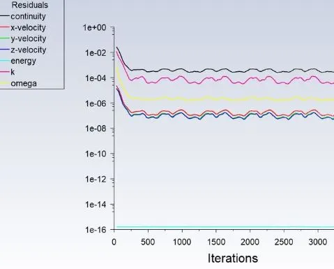
This plot shows that the results have converged.
- Drag coefficient:
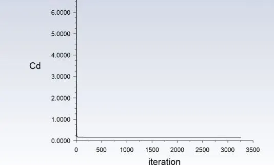
The C_d came to be as 0.16031272. This low value is because in the cad file, the legs are not considered.
- Lift coefficient:
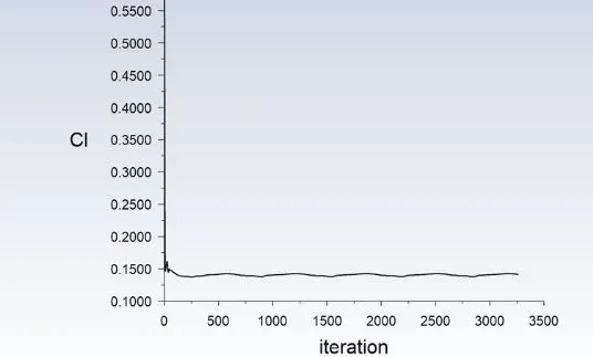
The C_l came to be as: 0.14046426
Contours of pressure and velocity:
- Static pressure contour:
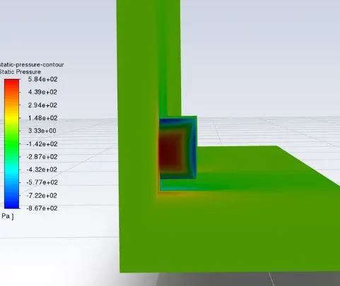
The respective high pressure regions can be visualized. The front of the car is subjected to high pressure.
- Velocity contour:
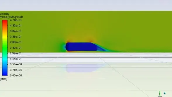
The wake region can be visualized in the back of the car. The wake region contributes to the development of drag. It is basically a re circulation zone, Flow separation occurs here.
Noise modelling:
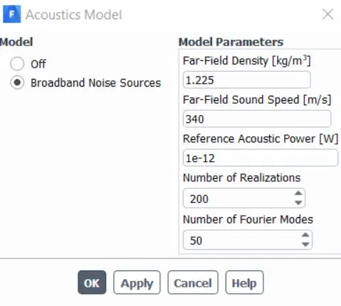
Inside the accoustics tab, broadband noise modelling is set on.
Contours :
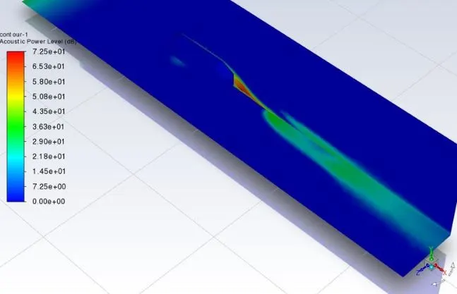
The accoustic power in decibel shows the high noise developing regions. The wake regions contribute significantly the noise
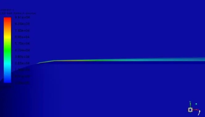
Lilys self noise source.
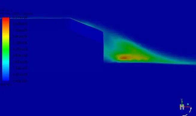
The wake region or the region of recirculation or the flow separation region contributes to the lilys noise distribution.
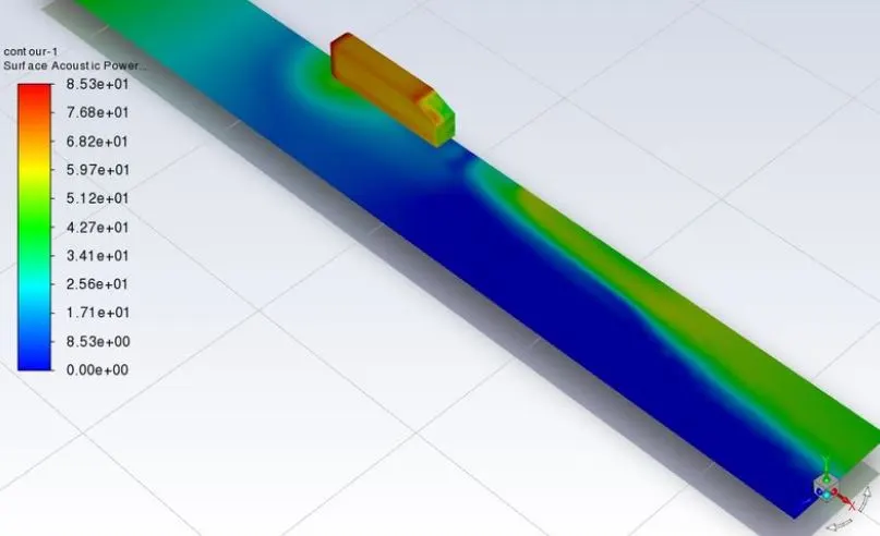
- Surface accoustic power (db)
- Conclusion:
- Broadband noise modelling over an Ahmed body is studied. High noise developing regions are found out in the process.
- Drag and lift coefficients are obtained.
- Detailed mesh is generated by calculating the y+ value.