Week 11- Assembly Workbench
Part Modeling and Assembly: The aim of this assignment is to get an hand's on experience on assembly environment and integration of assembly with the subsciquent workbenches. It is always necessary to create a project with flexiblity to changes, so that the upcoming modern advancement's can be easily adopted with respect to the current senariyo. This assignement act's as a core referance of working module in the CAD based industries.
Quick Return Mechanism: As the name suggest's the main purpose of this mechanism is to perform return motion faster then that of forward motion. It is mainly used in places where the force requirement for reverse motion is not needed, since it do not serve any purpose in reverse motion. The bellow shown Crank and Slotted Leaver Mechanism is an example of Quick Return Mechanism.
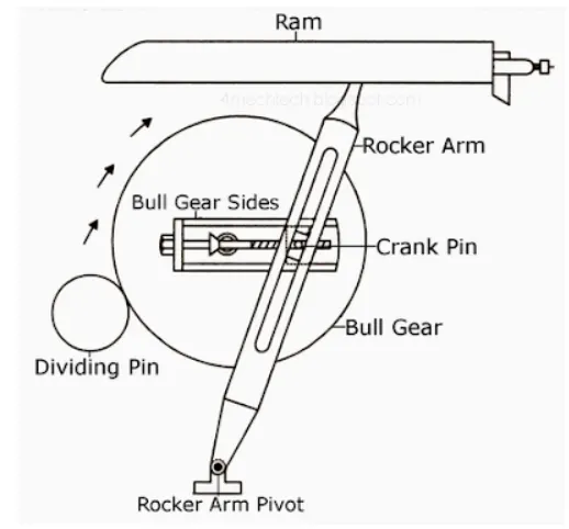
Crank and Slotted Leaver Mechanism
CV Joint: The purpose of the CV Joint is to transmit force and motion to functional components in an automotive system. It is mainly observed in engaging components like, transmission and differential, differential and wheel. In two wheel and four wheel drives the power from the differential is transmitted to wheels with the help of this system.
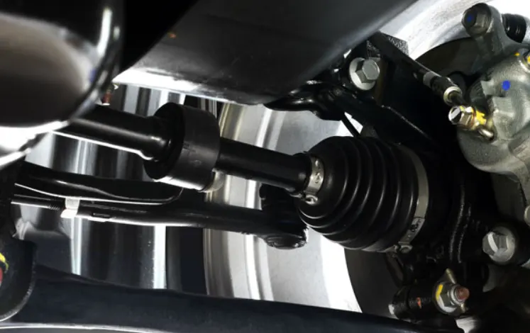
CV Joint
Part Modeling: The part modeling is done based on the drawing which is given as a input, as per the modeling requirement the parts are constrained together to transmit motion, so that the parts could be designed in such a way as it constrains with the subsciquent parts easily. Inorder to view the results easily and to adopt changes the main results are published. So that instead of making changes in each and every part, the parts which are engaged together with the subsciquent parts are changed automatically. Each and every company uses specific templets to enter its parts information as a customizable tool, which helps the industrial persons to proceed there work without errors. Quick Return Mechanism - Body 3 is shown as a example below.
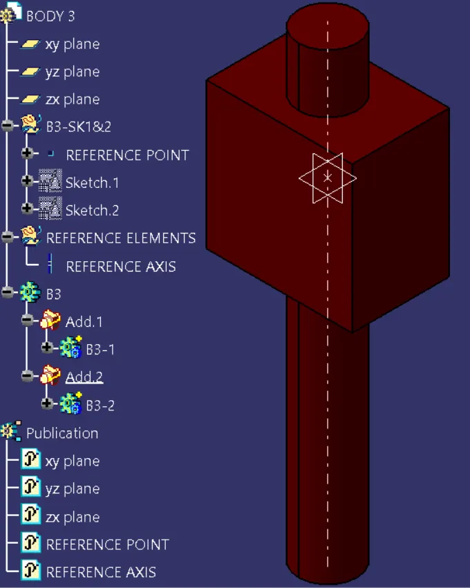
Quick Return Mechanism - Body 3
Assembly: It is done based on type of constrain introduced to it. Fully constrained assembly is considered to be structure, Successfully constrained assemply has force requirements on it and so it is said to be machine, Partially constrained assembly is said to be mechanism, it is left unconstrained along the specific path through which it moves and it has no force requirements. The assembly constrains are done with planes, points, axis and co-ordinates. Since constraining over serface or edges usually results in dificulties while making changes. Skeleton Reference in the below images are considered to be the zero referance for the entire assembly (i.e) it is the assembly co-ordinate. The overall assembly is done by keeping the skeleton co-ordinate as its common reference.
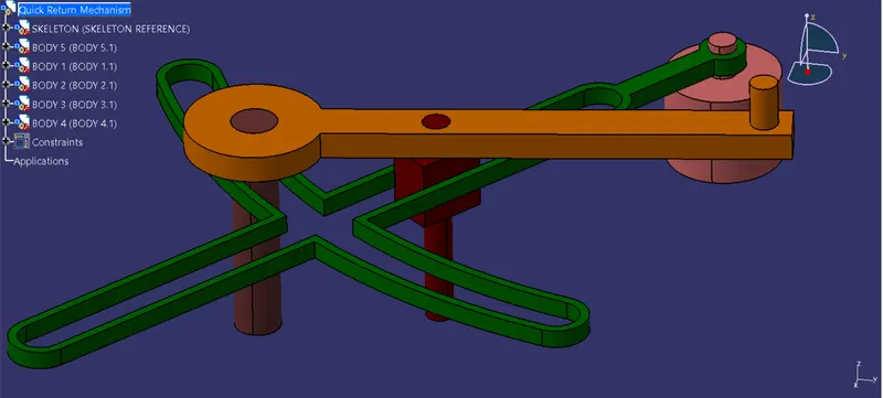
Quick Return Mechanism
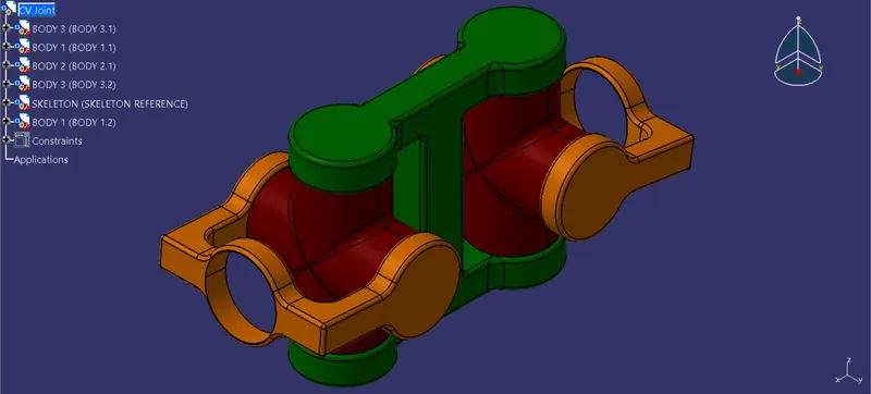
CV Joint Mechanism
Drawing: The communicative medium between the manufacturers and the designers is drawing. Hence, drawings must have the important details which are necessary to manufacture. An improper drawing approval may even lead to loss in production run. The technical drawings differs depending upon the industry in which a person work. The drawing for Quick Return Mechanism and CV Joint is done with a title block, ballons, bill of materials and various view representations. The final work is saved under save management, so that the consiquitive directory would be saved in a single click.
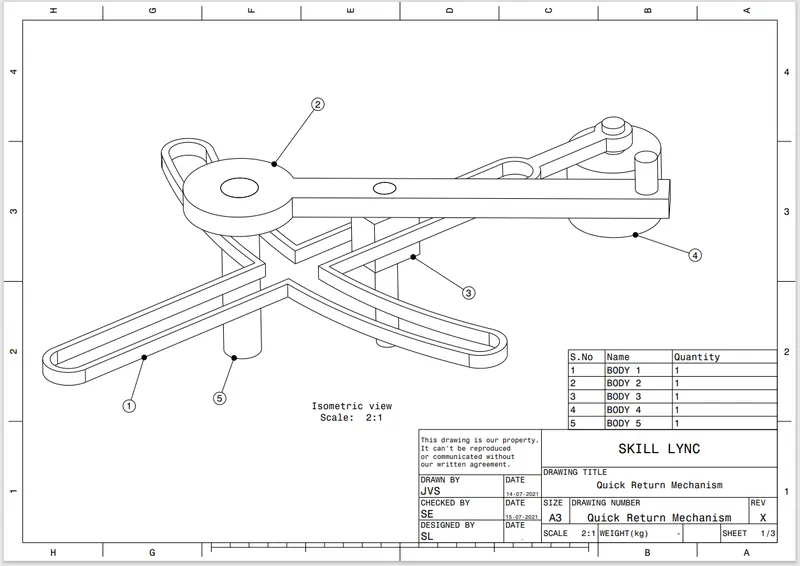
DWG of Quick Return Mechanism
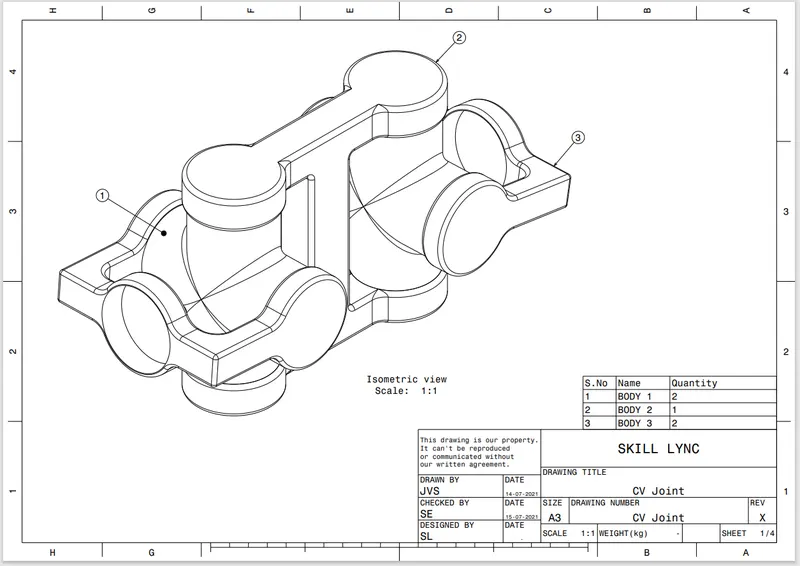
DWG of CV Joint