Week 11- Assembly Workbench
AIM:
To create 2 assemblies according to the content covered in the course videos. You will be provided with 2D diagrams of the components and you will have to first create the individual part files and then create a complete assembly of those part files in the assembly workbench. After creating the assembly, use the drafting tools to create a 2D drawing similar to the one given in the assignment folder.
SOFTWARE REQUIRED:
CATIA_V5 R21
Types of Assembly Design Approach :
In CATIA you can create assembly models by adopting two types of approaches. The first design approach is the bottom-up approach, and the second one is the top-down approach.Both these design approaches are discussed below.
1.Bottom-up Assembly
The bottom-up assembly is the most preferred approach for creating assembly models. In this of approach, the components are created in the Part Design workbench as (*.CATPart) file. Then the product (*.CATProduct) file is started and all the previously created components are inserted and placed in it using the tools provided in the Assembly Design workbench.
After inserting each component, constraints are applied to position them properly in the 3D space with respect to other components.
2.Top-down Assembly
In the top-down assembly design approach, components are created inside the Assembly Design workbench. Therefore, there is no need to create separate part files of the components.
This design approach is completely different from the bottom-up design approach. Here you have to start the product file first and then, one by one, create all components. Note that even though the components are created inside the product file, they are saved as individual part files and can be opened separately later.
PROCEDURES:
- initially, we creating a solid model by using given inputs( part dimensions).
- Once we get it, and we go to the assembly design workbench.
- Assembly design tool commands
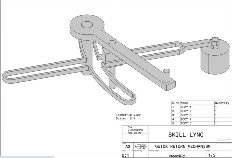
QUICK RETURN MECHANISM
A quick return mechanism is an apparatus that consists of a system of links with 3 turning pairs and a sliding pair that can convert rotary motion into reciprocating motion. The time taken for travel in return stroke is less than in forward stroke. A quick return mechanism is also known as a Crank and slotted lever quick return motion mechanism.
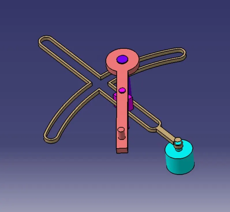
QUICK RETURN MECHANISM PARTS:
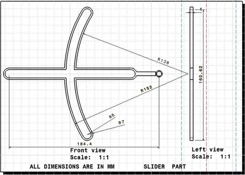
SLIDER PART
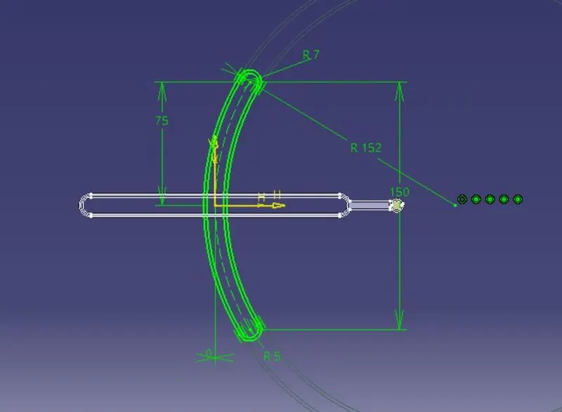
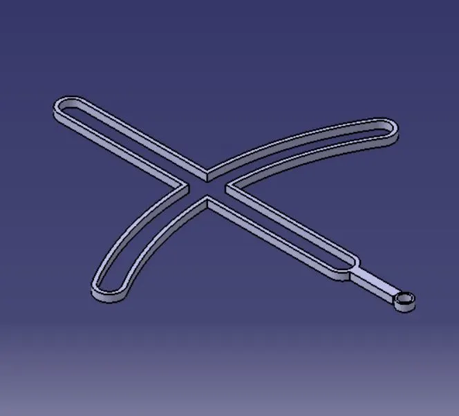
RETURN LEVER PART
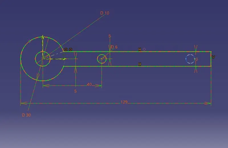
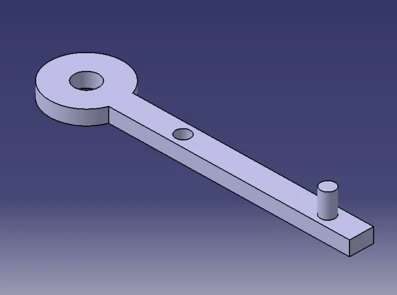
FIXER PART
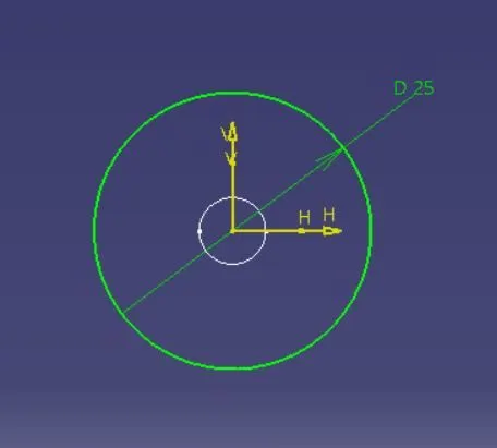
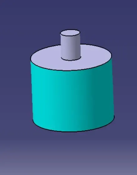
ROD PART
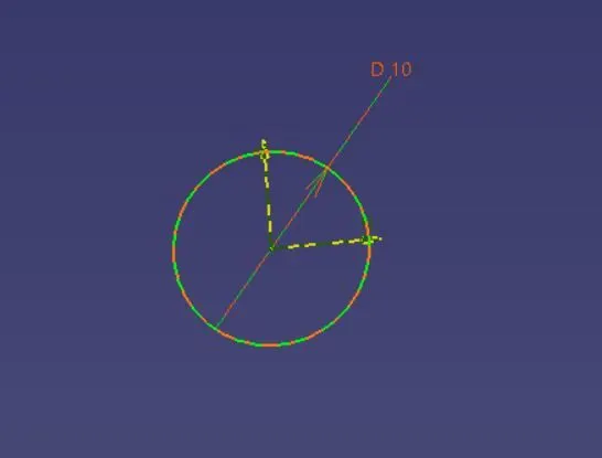
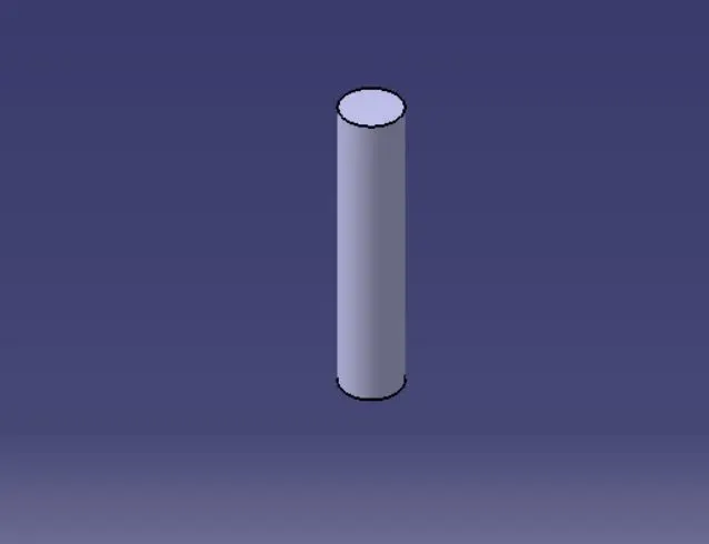
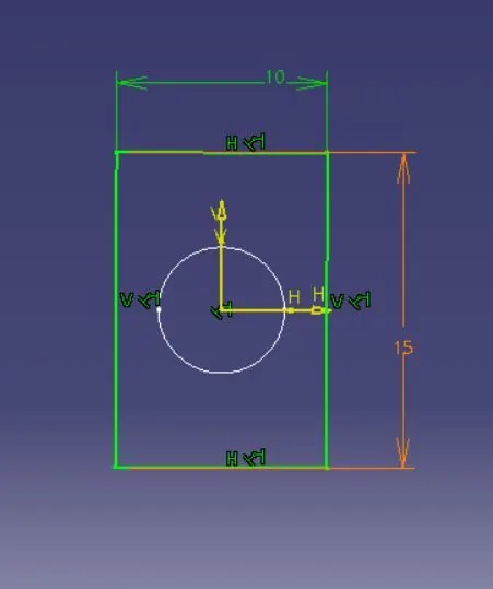
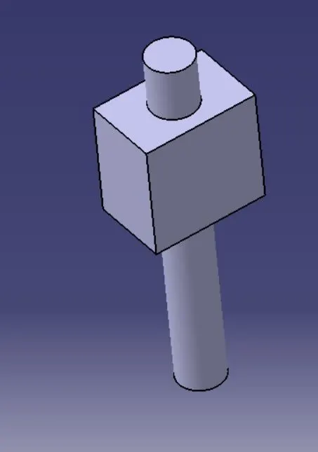
MOVABLE ROD PART
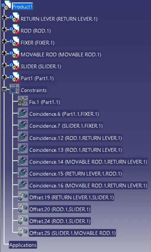
TREE STRUCTURE
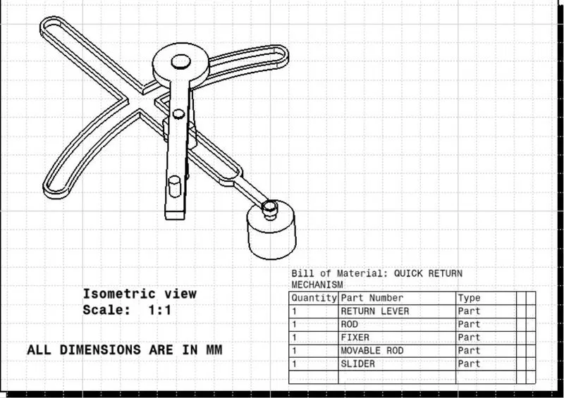
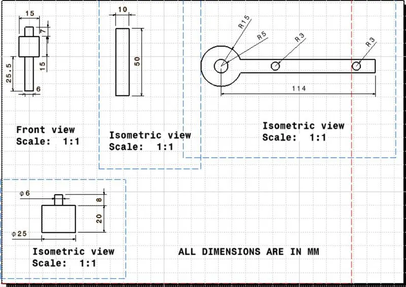
DRAFTING IMAGES
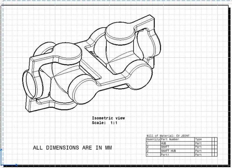
CV JOINT:
Constant velocity, or CV, joints are used to connect your vehicle’s transmission to your wheels. CV joints are part of the driveshaft and are used primarily on front-wheel drive vehicles, but they are also used in rear- and four-wheel drive vehicles. Each drive wheel has two CV joints: the inner joint connects the transmission to the axle, and the outer joint connects the axle to the wheel. The CV joint’s name comes from its ability to move with your vehicle’s suspension in any direction (if your vehicle hits a pothole or an uneven surface) and still be able to keep the drive wheels moving at a constant velocity. The CV joint is a very special joint: it connects two different rotating shafts. These two rotating shafts are stuck in a fixed position.
CV JOINT PARTS
ISOMETRIC VIEW
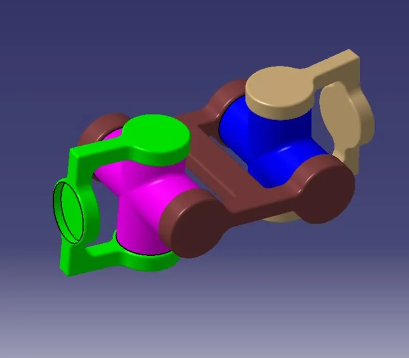
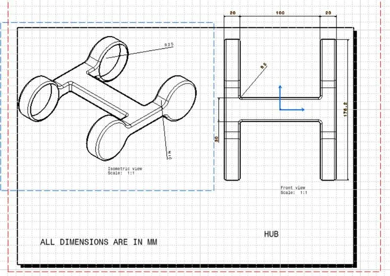
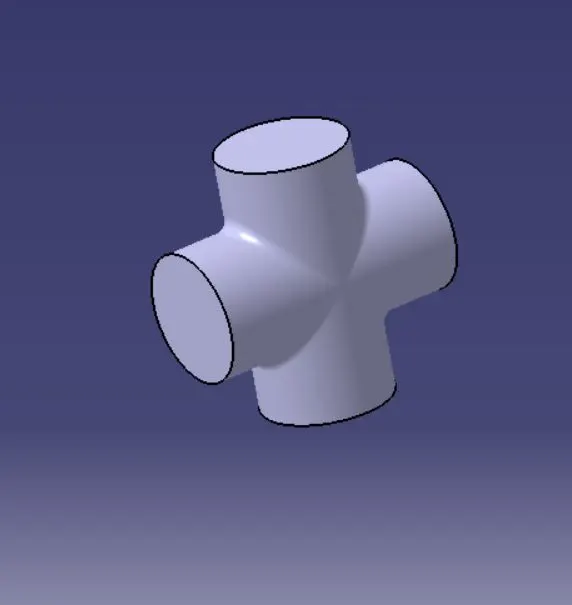
HUB PART
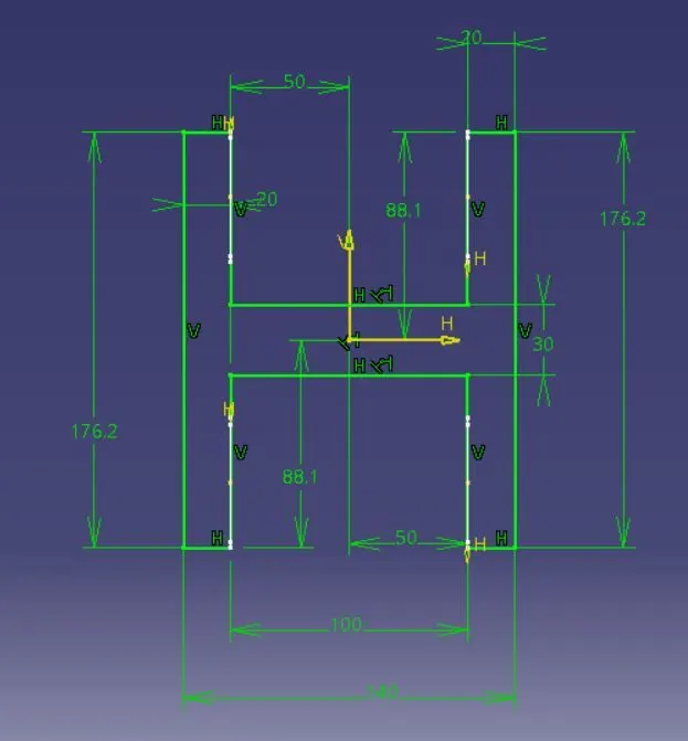
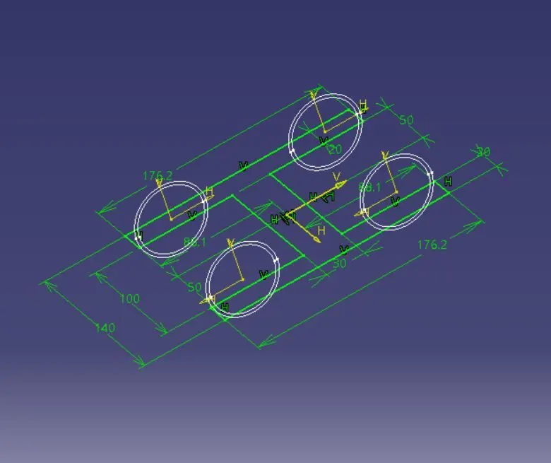
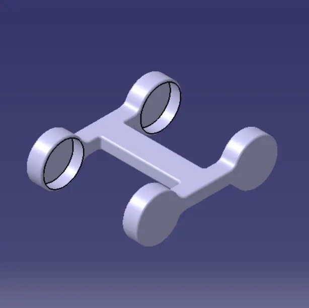
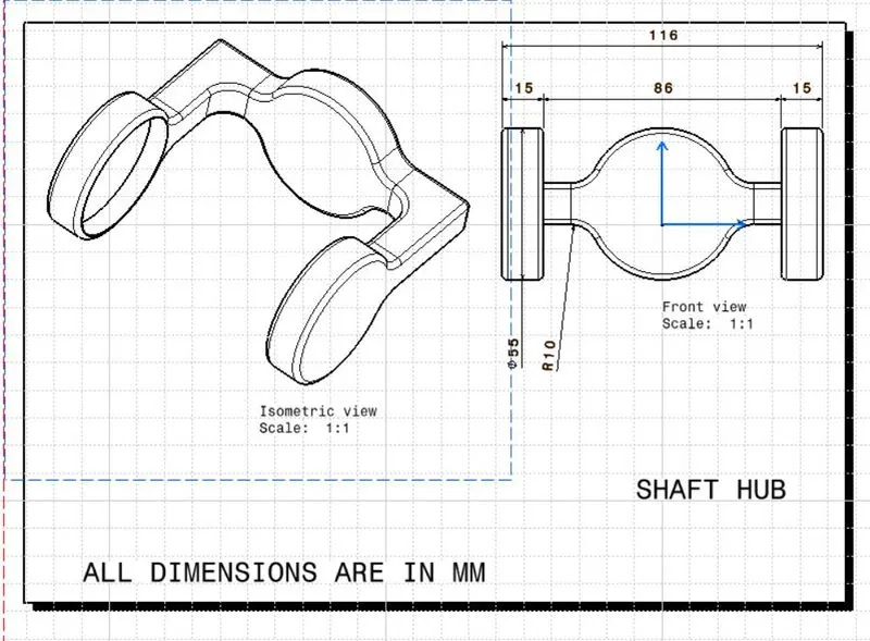
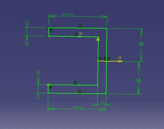
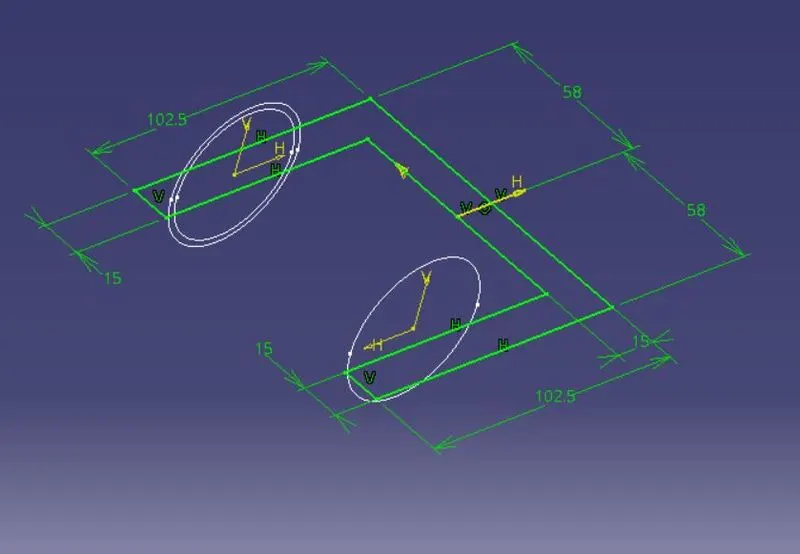
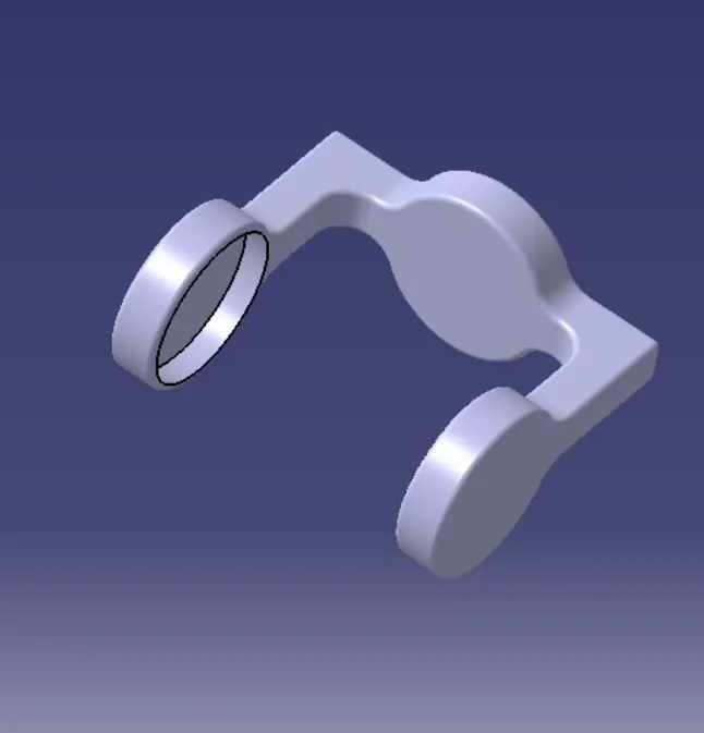
SHAFT HUB
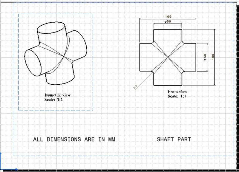
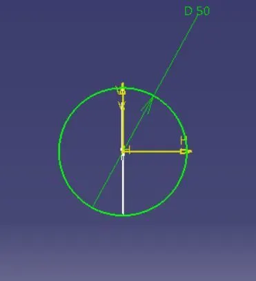
SHAFT PART
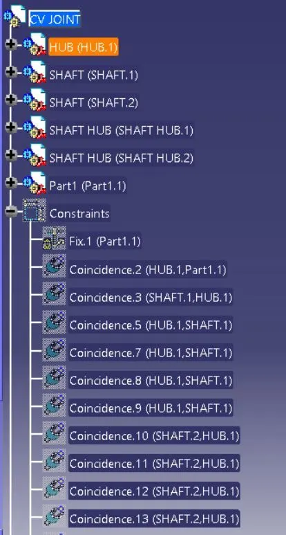
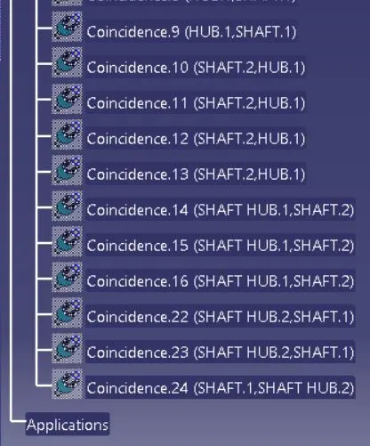
TREE STRUCTURE
DRAFTING IMAGES