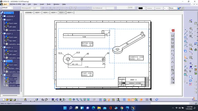
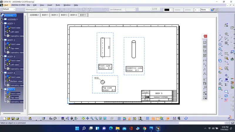
Week 11- Assembly Workbench
Model 1
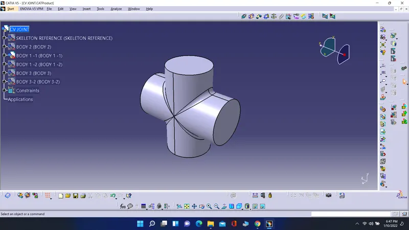
Body 1
- Create a circle of the given diameter and then pad it.
- Create a second circle on the perpendicular plane to the first one and then pad it in different body.
- Now using boolean operation add them together.
- Give a fillet.
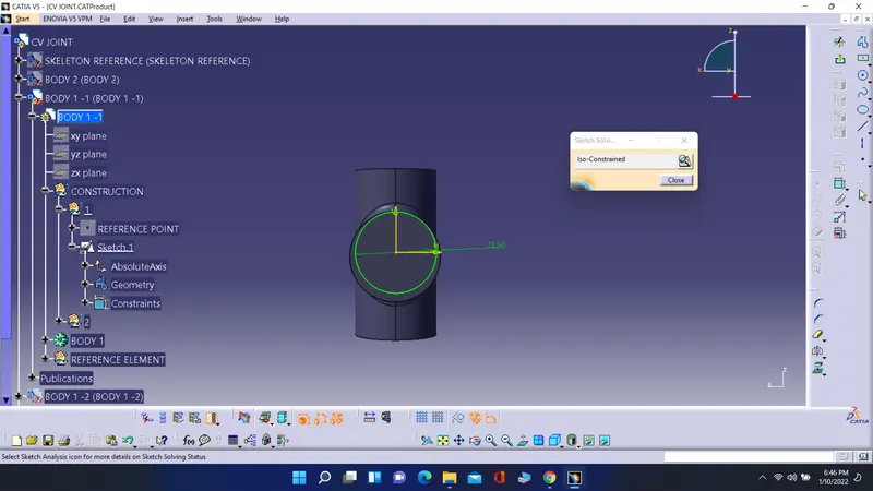
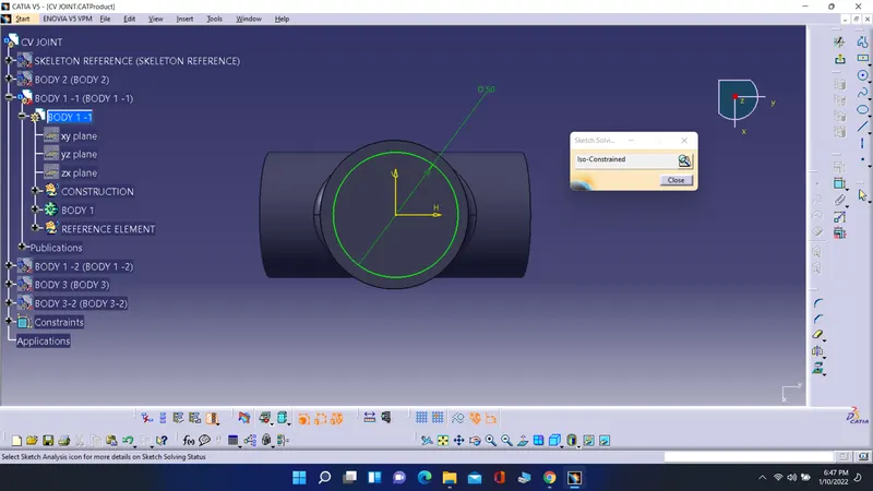
Body 2
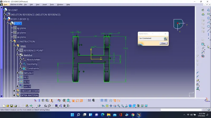
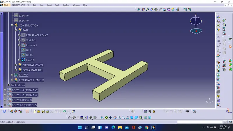
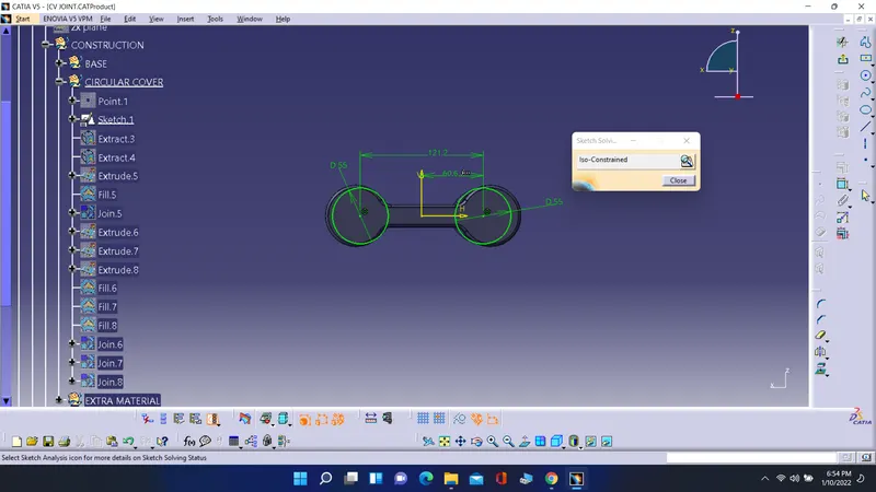
- First create a sketch of the base and create a surface of that.
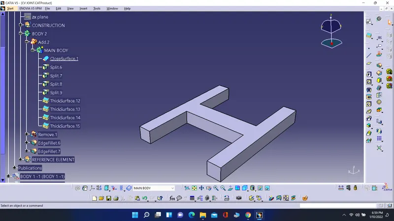
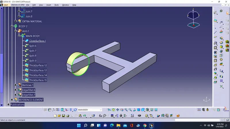
- Now using fill surface command create a surface for both side then join them together to create a close surface then create a body using closed body command.
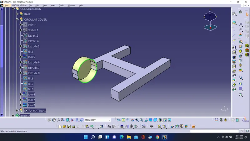
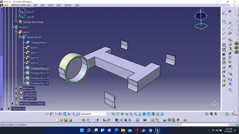
- Now create circle and then create a extrude surface for proper location and then split the body using that surface now using fill surface fill the one face which is required then give a thickness to the surface.
- Repeat this process for all the corners.
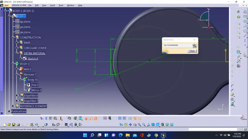
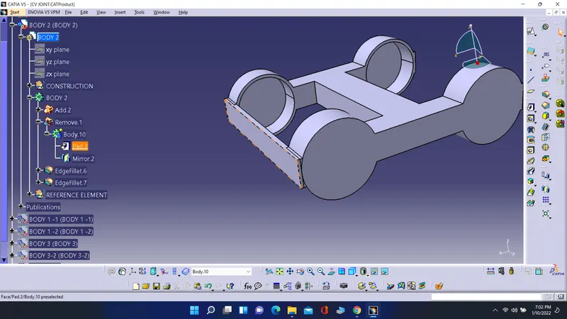
- Now create a profile of the extra material then pad it till the body and using boolean operation remove that material from the main body.
- Give a proper fillet to the edges.
Body 3
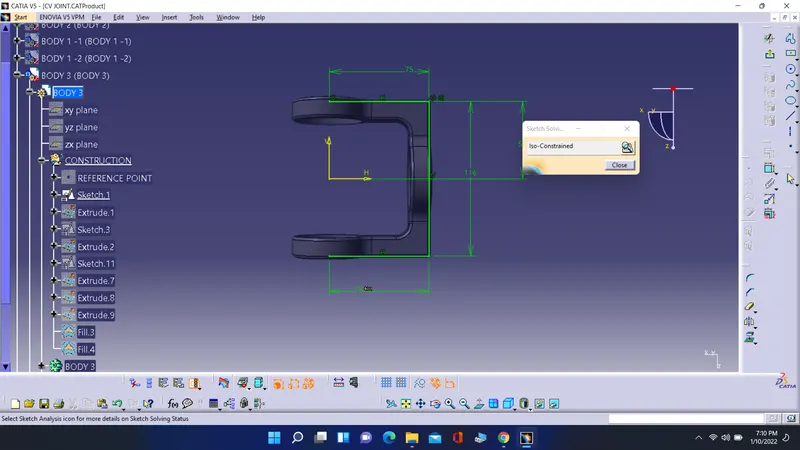
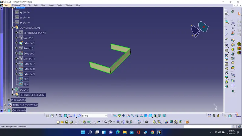
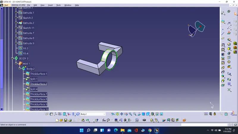
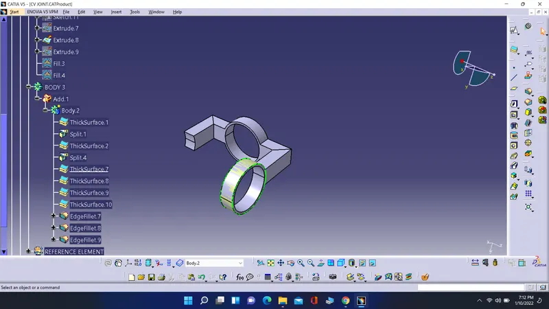
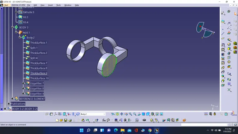
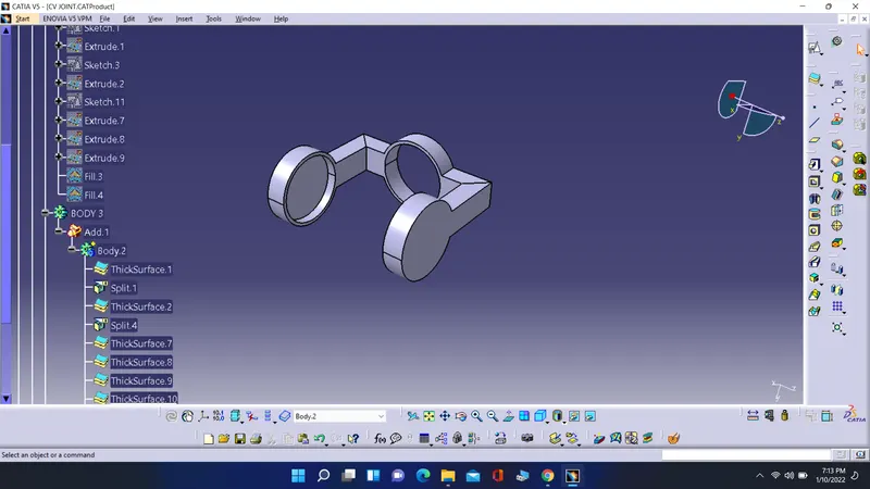
- First create a sketch for the base of the mody.
- Now using extrude surface command create a surface of the sketch.
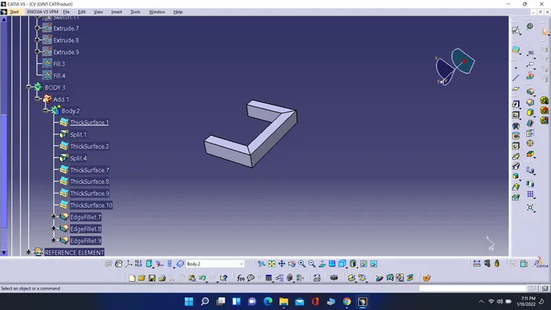
- Now give thickness to the surface.
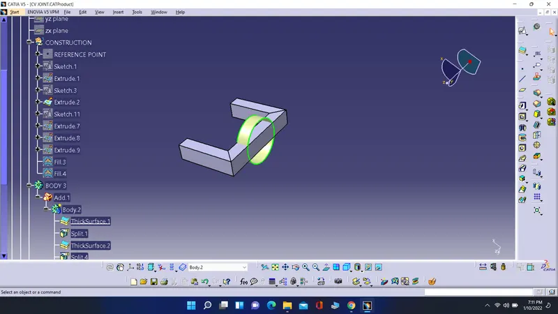
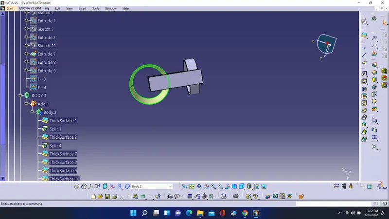
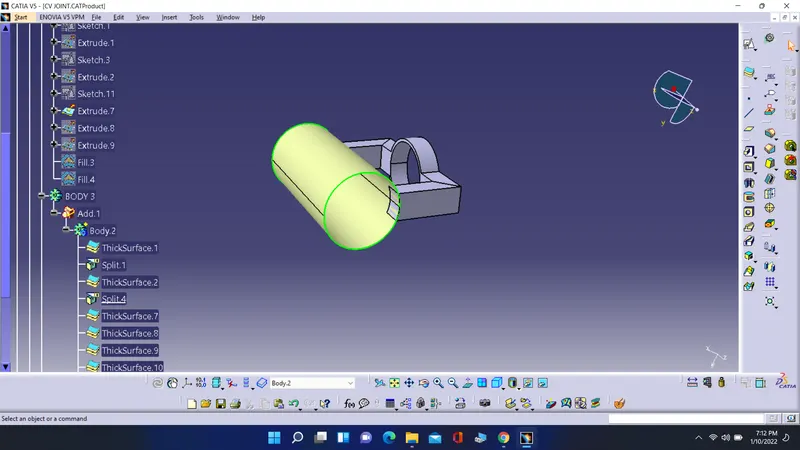
- Now create a circle and using that create a surface.
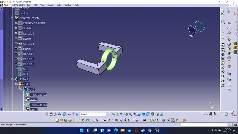
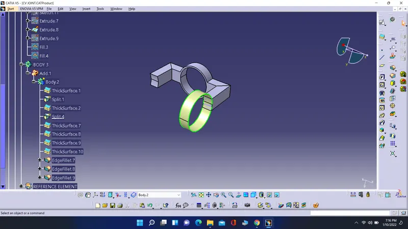
- Split the body using the surface and then give a thickness.
- Now on another side create a circle and the create a surface again split the body and give a thickness.
- Now using fill surface command create a end of that circle and give a thickness to only filled surface of 7mm.
- Now give required fillet to the edges.
Assembly of the model 1
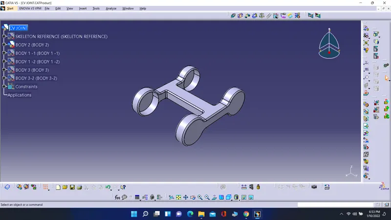
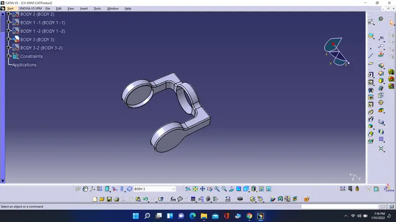
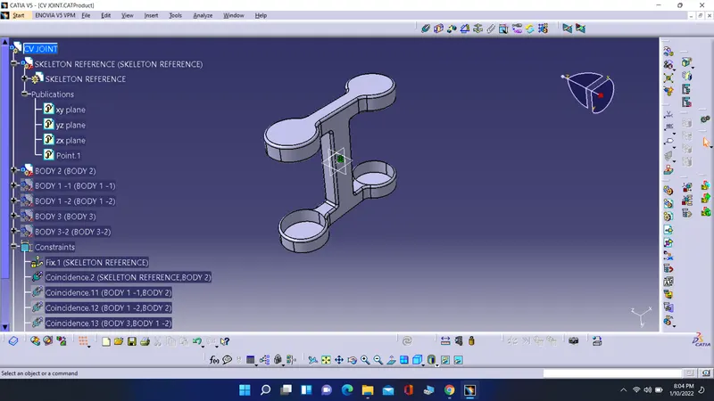
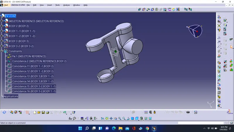
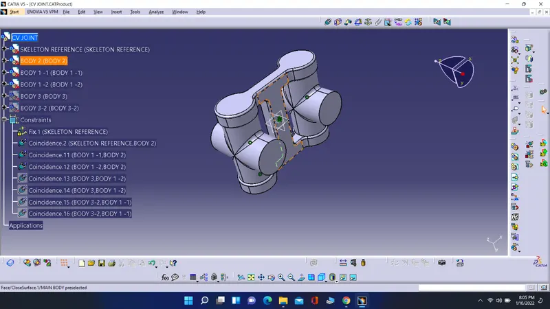
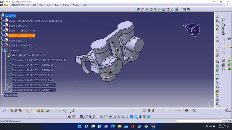
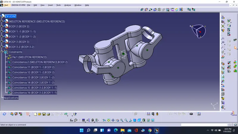
- Here first i craeted a skeleton for the assembly origin and then give it a fix constraint.
- Now i inserted a body to as it is the base and its fix component then give it a point to point constraints.
- Now i inserted a body 1 and then give it a axis constraint with body 2.
- For another side just copied the body 1 and then using paste special option breaks link option create a new part which is same as body 1. then again give it a axis constraint for another side,
- Now inserted a body 3 then give it a axis constaint with body 1 and and again followed a same procedure of coping the body and paste special then give a axis constaint.
Drawings of the model 2
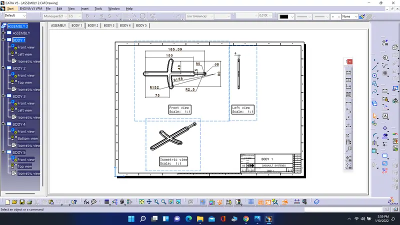
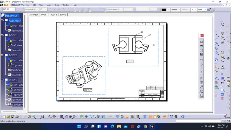
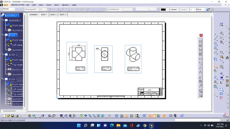
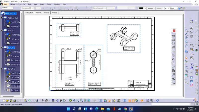
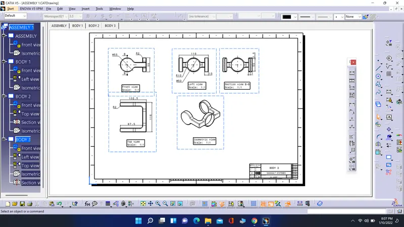
- Here are some drawings of the model 2 parts.
Model 2
Body 1
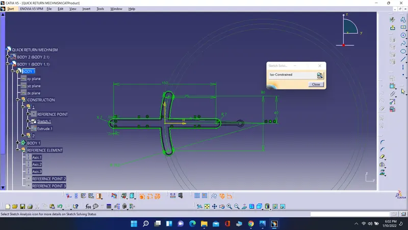
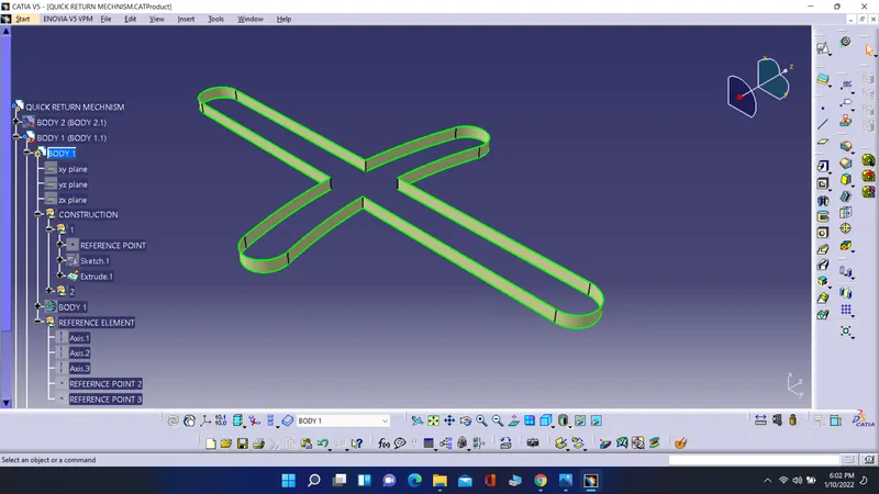
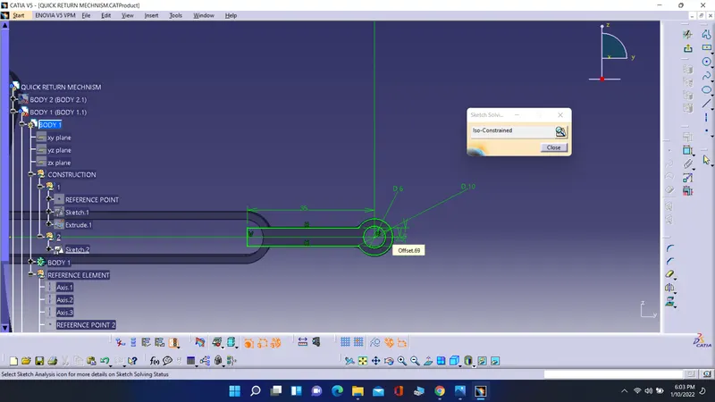
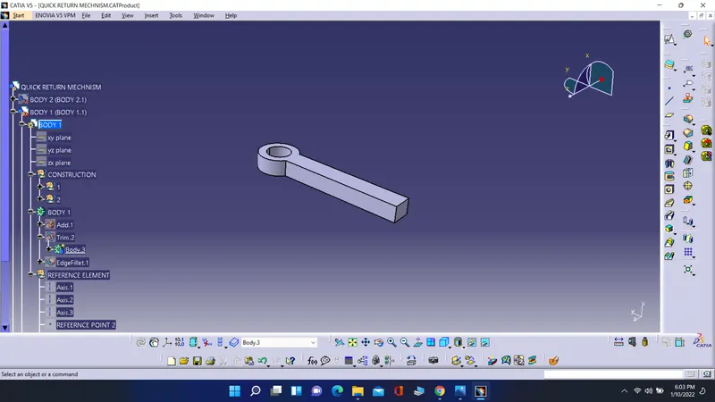
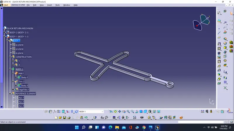
- FIrst created a sketch for the first part of the body and then created a surface and then gave a thickness of 2mm.
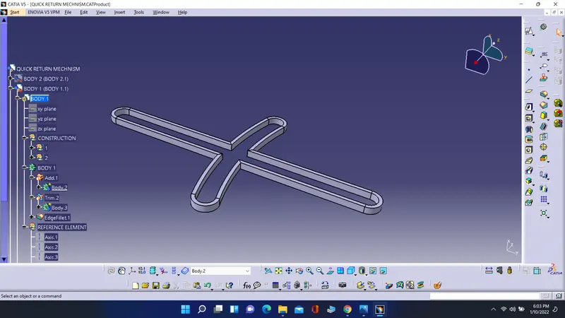
- Now created a second part of the body and then gave a pad to it.
- Now using boolean operation unitrim the second part to join them together
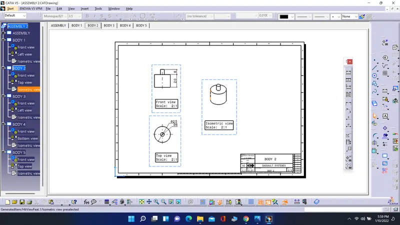
Body 2
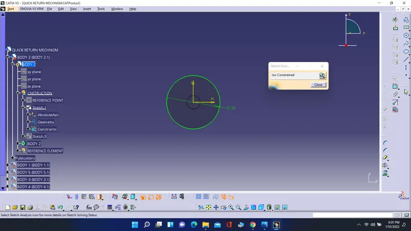
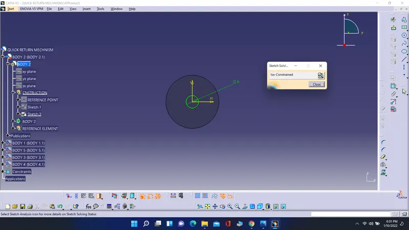
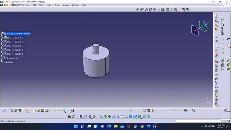
- First create a circle of given diameter and then pad it.
- Now create a second circle of given diameter and then pad it.
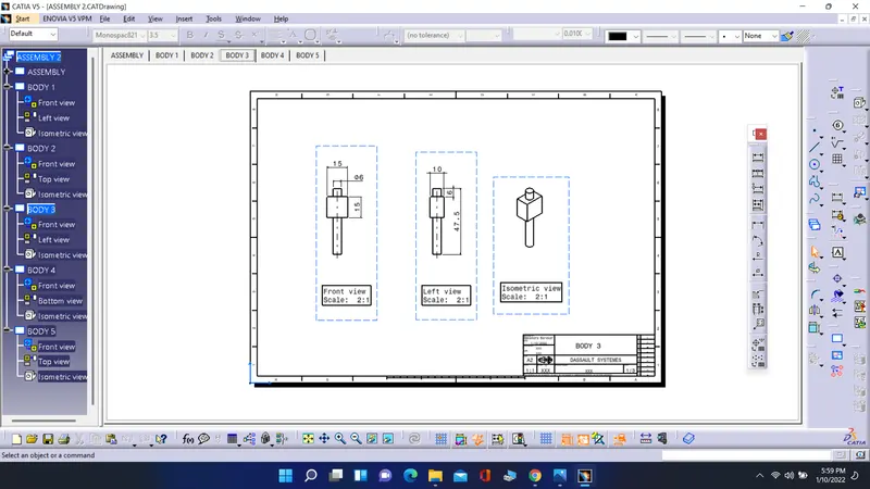
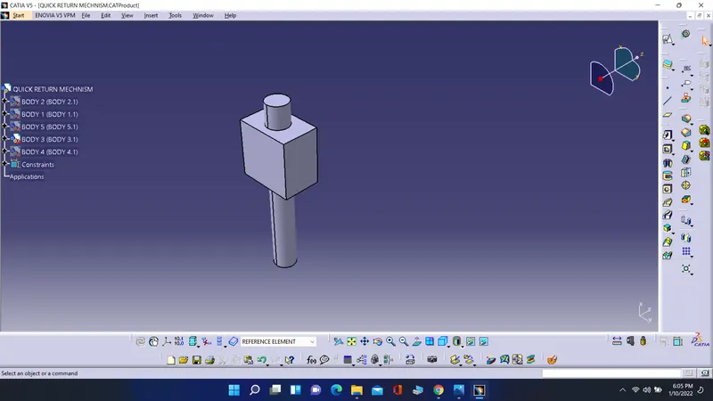
Body 3
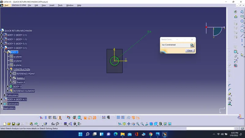
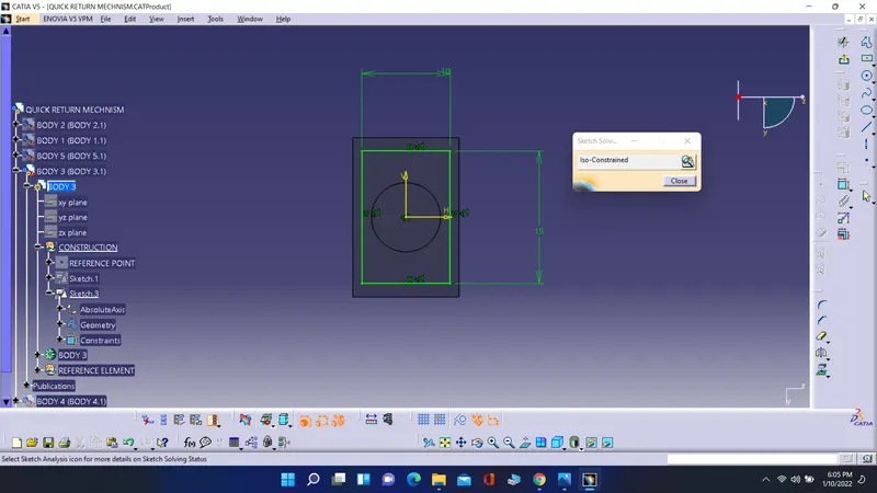
- First create a circle for the pin and then pad to longest length to it.
- then create a rectangle on the plane and then pad it.
Body 4
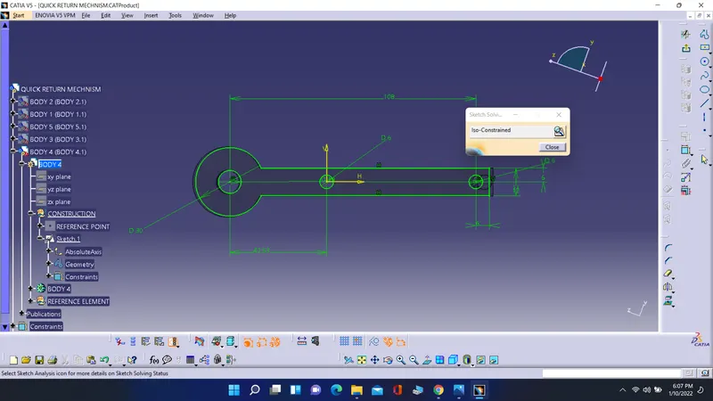
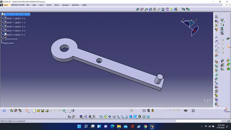
- First create a sketch of the part with holes.
- Then use multi pad to pad it for whole base its 4mm and for the last pin its 16mm.
Body 5
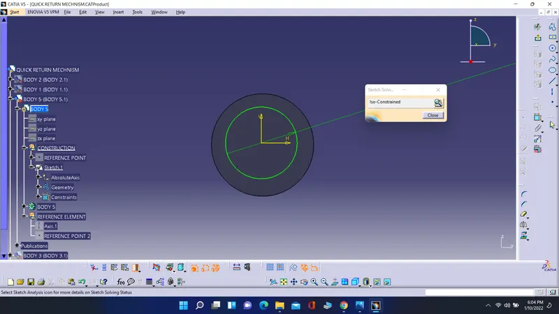
- First create a circle and then give a pad.
Assembly of model 2
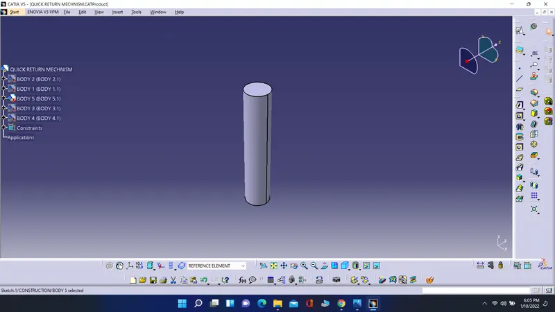
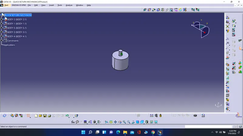
- First insert a body 2 and give a fix constraints to it.
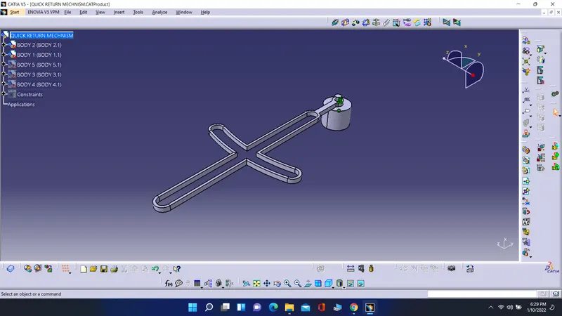
- Now insert a body 1 and give a point and axis constraints with body 2.
- Now insert a body 5 and give axis and point constraints with body 1.
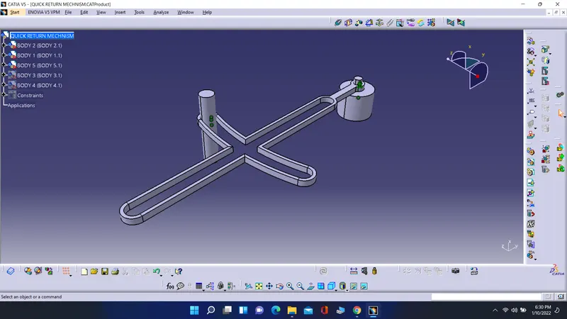
- Now insert a body 3 and give a offset constraint with body 1 and right plane constraint with body 1.
- Now insert a body 4 and give a axis constaint with body 5 and body 3.
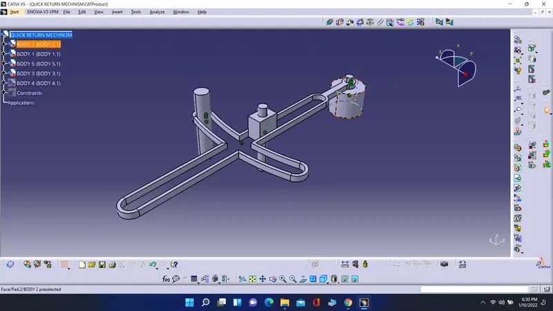
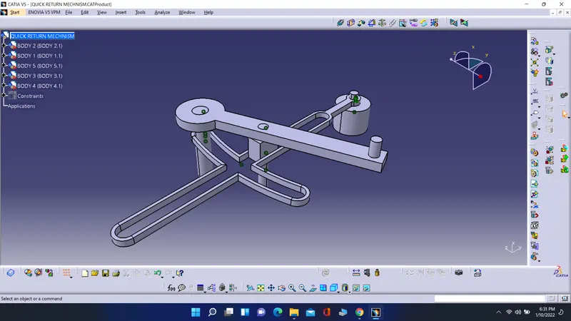
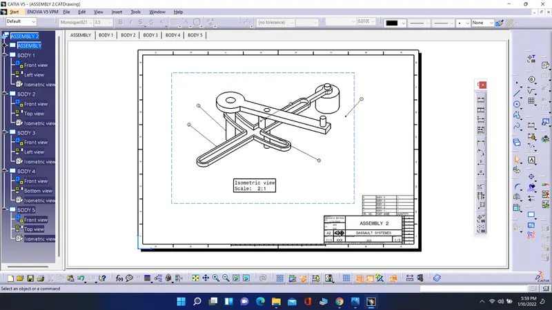
Drawing of the model to
- There are some drawings of the model 2 components and assembly